Table of Contents
Advertisement
Quick Links
WARNING
Improper installation, adjustment, alteration, service
or maintenance can result in death, injury or
property damage. Read the Installation, Operation
and Service Manual thoroughly before installing or
servicing this equipment.
Installation must be done by an electrician qualified
in the installation and service of control systems
for heating equipment.
© 2019 Roberts-Gordon LLC
UltraVac
Infrared Heating
Installation Manual
Installer
Please take the time to read and understand
these instructions prior to any installation.
Installer must give a copy of this manual to the owner.
Owner
Keep this manual in a safe place in order to provide
your service technician with necessary information.
Roberts-Gordon LLC
1250 William Street
P.O. Box 44
Buffalo, New York 14240-0044
Telephone: +1.716.852.4400
Fax: +1.716.852.0854
Toll Free: 800.828.7450
www.robertsgordon.com
™
PATENTED
Controls for
Modulating
CORAYVAC
Systems
P/N 10081601NA Rev M 6/19
®
Advertisement
Table of Contents

Related Manuals for Roberts Gorden UltraVac URVCCL


Summary of Contents for Roberts Gorden UltraVac URVCCL
- Page 1 UltraVac ™ PATENTED Controls for Modulating ® CORAYVAC Infrared Heating Systems Installation Manual Installer WARNING Please take the time to read and understand Improper installation, adjustment, alteration, service these instructions prior to any installation. or maintenance can result in death, injury or Installer must give a copy of this manual to the owner.
-
Page 3: Table Of Contents
TABLE OF CONTENTS SECTION 1: Introduction............1 SECTION 6: ULTRAVAC™ BMS Link Controller ....35 1.1 Safety ................1 6.1 ULTRAVAC™ BMS Link Controller Overview .... 35 1.2 Safety Labels and Their Placement......1 6.2 ULTRAVAC™ BMS Link Controller Requirements..36 1.3 California Proposition 65 ..........1 6.3 Technical Data ............ -
Page 5: Section 1: Introduction
SECTION 1: I NTRODUCTION SECTION 1: INTRODUCTION 1.1 Safety 1.3 California Proposition 65 In accordance with California Proposition 65 require- Your Safety is Important to Us! ments, a warning label must be placed in a highly This symbol is used throughout visible location on the outside of the equipment (i.e., the manual to notify you of near equipment’s serial plate). -
Page 6: Corayvac Design Requirements
® ROBERTS GORDON ULTRAVAC™ C ONTROLLER NSTALLATION ANUAL ranty. See Page 61, Section . ROBERTS GORDON ® ULTRAVAC™ Software requires a PC (not supplied) running Windows ® 95 or ® higher, with a Pentium class processor and at least 64k of RAM. The controller, variable frequency drive, burners, repeater, pump and outside air blower must be electrically grounded in accordance with the National... - Page 7 SECTION 1: I NTRODUCTION FIGURE 1: Connected Components 3 of 65...
- Page 8 ® ROBERTS GORDON ULTRAVAC™ C ONTROLLER NSTALLATION ANUAL Connected Components (continued) 4 of 65...
-
Page 9: Carton Contents
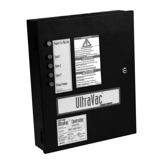
SECTION 1: I NTRODUCTION 1.9 Carton Contents URVSC: ULTRAVAC™ Satellite Controller ULTRAVAC™ Controller Inside View ULTRAVAC™ Installation Manual (P/N 10081601NA) URVCCL: ULTRAVAC™ Central Controller with TCP/IP Communication Module ULTRAVAC™ Software (P/N 100816CDNA) contains: ULTRAVAC™ Software, ULTRAVAC™ Software Manual. Inside View (P/N 10081601NA) ULTRAVAC™... - Page 10 ® ROBERTS GORDON ULTRAVAC™ C ONTROLLER NSTALLATION ANUAL URVCCM: ULTRAVAC™ Central Controller with Modem Inside View ULTRAVAC™ Controller with Modem Installed Repeater (optional) ULTRAVAC™ Software (P/N 100816CDNA) contains: Supplied w/24 VAC ULTRAVAC™ Software, ULTRAVAC™ Software Manual. transformer inside NEMA 1 (P/N 10081601NA), ULTRAVAC™...
- Page 11 SECTION 1: I NTRODUCTION URVCCR: ULTRAVAC™ Central Controller with RS-485 Converter Inside View ULTRAVAC™ Controller with Modem Installed Repeater (optional) Supplied w/24 VAC ULTRAVAC™ Software (P/N 100816CDNA) contains: transformer inside NEMA 1 ULTRAVAC™ Software, ULTRAVAC™ Software Manual. enclosure (P/N 10060153) (P/N 10081600NA), ULTRAVAC™...
- Page 12 ® ROBERTS GORDON ULTRAVAC™ C ONTROLLER NSTALLATION ANUAL URVU: ULTRAVAC™ Unitary Controller Inside View ULTRAVAC™ Unitary Controller URVBNC: ULTRAVAC™ BMS Link Controller 24VAC+ 24VAC- VDC- VDC+ NETWORK ROUTER PORT 5 PORT 4 PORT 3 PORT 2 PORT 1 ULTRAVAC™ Software (P/N 100816CDNA) contains: ULTRAVAC™...
-
Page 13: Standard Parts List
SECTION 1: I NTRODUCTION 1.10 Standard Parts List Table 1: Contents of ULTRAVAC™ Controller and Accessories Part No. Description URVCCL ULTRAVAC™ Central Controller (with TCP/IP Communication Module, Software & Manual), Including: URVSC Controller, ULTRAVAC™, 1 Pump 3 Zones (Satellite Control & Manual) 10080440 TCP/IP Communication Module 10081501 Outdoor Sensor... - Page 14 ® ROBERTS GORDON ULTRAVAC™ C ONTROLLER NSTALLATION ANUAL Related Accessories 10080410 Cable Package, PC Connection 10080430 RS-485 Converter with 9 V Power Supply 10080440 TCP/IP Communication Module 10080600 Telephone Sharing Device, 4-Port 10081500 Sensor, Adjustable Indoor, °F, URV 10081501 Sensor, Outdoor, URV 10081502 Sensor, Adjustable Indoor, °C, URV 90602450 Voltage Surge Supresser 277/480 V...
- Page 15 SECTION 1: I NTRODUCTION FIGURE 2: Example Site Layout NOTE: Conceptual drawing, not to scale. Venting not shown. 11 of 65...
-
Page 16: Section 2: Specifications
® ROBERTS GORDON ULTRAVAC™ C ONTROLLER NSTALLATION ANUAL SECTION 2: SPECIFICATIONS 4-20m A Resistance 2.1 ROBERTS GORDON ® ULTRAVAC™ Controller Dry contact 2.1.1 Standard Enclosure Analog Output: Construction: 16 gauge painted steel, hinged One Analog Output 0-10 Vdc door, removable knockouts Digital Inputs: provided. -
Page 17: Temperature Sensors
SECTION 2: S PECIFICATIONS Construction: Fabricated in accordance with UL Dimensions: W x H x D specifications from code gauge steel, (in): 6.3 x 3.6 x 1.8 NEMA 1. (cm): 16.0 x 9.1 x 4.6 Finish: Gray, Non-Metallic UV-Rated Construction: Polycarbonate enclosure with clear front cover, 4 screw cover closure. - Page 18 ® ROBERTS GORDON ULTRAVAC™ C ONTROLLER NSTALLATION ANUAL specifications from code gauge steel, NEMA 1. Dimensions: W x H x D (in): 10 x 8 x 8 (cm): 25 x 20 x 20 Rated Current: Volts: 230 V / 3 Ø Voltage Surge Suppressor 277 / 480 V Construction: NEMA 2X Enclosure Volts:...
- Page 19 SECTION 2: S PECIFICATIONS FIGURE 3: ROBERTS GORDON ® ULTRAVAC™ Controller Specifications Note: To ensure robust control signaling: Do not run line voltage wiring through bottom section of enclosure that houses the control board. Do not run low voltage wiring through top section of enclosure that houses the relay board.
-
Page 20: Variable Frequency Drive (Vfd)
® ROBERTS GORDON ULTRAVAC™ C ONTROLLER NSTALLATION ANUAL 2.8 Variable Frequency Drive (VFD) 2.8.1 Enclosure Standard Models Construction: 14 gauge painted steel, mounting .75 HP, 230 V Drive (used with EP-203 pump) panel included, left-hinged door, (P/N VFD75230 or VFD75230N4) vented. - Page 21 SECTION 2: S PECIFICATIONS FIGURE 4: Variable Frequency Drive Components (Factory pre-wiring shown) 17 of 65...
-
Page 22: Section 3: Installation
® ROBERTS GORDON ULTRAVAC™ C ONTROLLER NSTALLATION ANUAL SECTION 3: INSTALLATION maximum ambient temperature does not exceed 104°F (40°C). Avoid installing the VFD in mezza- DANGER nines, direct sunlight, or near external heat sources because these locations usually have unpredictable temperature rises. Note that the maximum distance from the controller to any sensor is 300' (120 m). -
Page 23: Cable Requirements
SECTION 3: I NSTALLATION 3.3 Cable Requirements: • Communications between Multiple Controllers (RS-485) As per individual building specification for class of One twisted pairs of 22 AWG minimum or equiva- cable to be used. Use copper conductors only. lent shielded cable; Belden #3105A. 3.4 Check Installation Materials 3.4.5 ULTRAVAC™... -
Page 24: Electrical Installation Requirements Of Ultravac™ Controller
® ROBERTS GORDON ULTRAVAC™ C ONTROLLER NSTALLATION ANUAL VFD20575 or VFD20575N4 via an output from the relay board switched through a VFD20230 or VFD20230N4 12 AWG designated relay. VFD75460 or VFD75460N4 14 AWG VFD20460 or VFD20460N4 14 AWG 3.7 Variable Frequency Drive Requirements •... -
Page 25: Indoor Sensor Placement
SECTION 3: I NSTALLATION 3.8 Indoor Sensor Placement or control board damage. Refer to Page 23, Figure 9 and Page 25, Figure 10 for wiring details. The sensor measures the air temperature in the building. It is important that the sensor is located in an area within the heated zone at occupant level. -
Page 26: Section 4: Typical External Diagrams
® ROBERTS GORDON ULTRAVAC™ C ONTROLLER NSTALLATION ANUAL SECTION 4: TYPICAL EXTERNAL DIAGRAMS DANGER Electrical Shock Hazard Disconnect electric before service. Controller must be properly grounded to an electrical source. Failure to follow these instructions can result in death or electrical shock. 22 of 65... - Page 27 SECTION 4: T YPICAL XTERNAL IAGRAMS FIGURE 9: ROBERTS GORDON ® ULTRAVAC™ Central Controller External Wiring 23 of 65...
- Page 28 ® ROBERTS GORDON ULTRAVAC™ C ONTROLLER NSTALLATION ANUAL ROBERTS GORDON ® ULTRAVAC™ Central Controller External Wiring (continued) 24 of 65...
- Page 29 SECTION 4: T YPICAL XTERNAL IAGRAMS FIGURE 10: ROBERTS GORDON ® ULTRAVAC™ Satellite Controller External Wiring 25 of 65...
- Page 30 ® ROBERTS GORDON ULTRAVAC™ C ONTROLLER NSTALLATION ANUAL ROBERTS GORDON ® ULTRAVAC™ Satellite Controller External Wiring (continued) 26 of 65...
-
Page 31: Section 5: Communications
SECTION 5: C OMMUNICATIONS SECTION 5: COMMUNICATIONS shielded twisted pair communication wiring. One ROBERTS GORDON ® ULTRAVAC™ Controller See Page 28, Figure 12. per building (called the "central controller") must have equipment for remote communications to a PC. To interface with ULTRAVAC™ controllers through a This equipment consists of either a modem chip, an Local Area Network (LAN), a TCP/IP Communication RS-485 converter, or a TCP/IP communications... -
Page 32: Converter For Central Controller
® ROBERTS GORDON ULTRAVAC™ C ONTROLLER NSTALLATION ANUAL 5.2 RS-485 Converter for Central Controller For remote on-site viewing of system status and For communication cable requirements see Page 19, settings of any controller, use the RS-485 converter Section 3.3. to connect a single PC (9 pin serial port) to the RS- If multiple ULTRAVAC™... -
Page 33: Tcp/Ip Communication Module
SECTION 5: C OMMUNICATIONS 5.3 TCP/IP Communication Module from the controller to computers on the LAN via Ethernet cable plugged into the RJ45 jack on the For remote on-site viewing of system status and module. A setup procedure must be performed on settings of any controller, use the TCP/IP communi- the module upon installation to create its IP address cation module to connect the controllers to a Local... -
Page 34: Direct Connect
® ROBERTS GORDON ULTRAVAC™ C ONTROLLER NSTALLATION ANUAL FIGURE 14: TCP/IP Communication Module Wiring It is important that the module power wire is connected as shown (black=5 V- / red= 5 V+) wire orientation. Make sure to verify connection before connecting to the control board. Description Part Number Kit, TCP/IP Communication... - Page 35 SECTION 5: C OMMUNICATIONS FIGURE 15: 9 Pin Adapter for PC Description Part Number PC Connection Cable Package 10080410 31 of 65...
-
Page 36: Communications Between Multiple Roberts Gordon
® ROBERTS GORDON ULTRAVAC™ C ONTROLLER NSTALLATION ANUAL 5.5 Communications Between Multiple ROBERTS GORDON ® ULTRAVAC™ Controllers system status and settings can be viewed for any of If more than one ROBERTS GORDON ® the controllers on the network. ULTRAVAC™ Controller is installed in a building, the controllers’... - Page 37 SECTION 5: C OMMUNICATIONS 5.5.1 Repeater If the RS-485 communications wire length is above 4000' (1219 m), a repeater must be used to extend the signal. The repeater can also be used to install in different methods: • To extend communications beyond the standard 4000' (1219 m) limitation. See Page 33, Figure 17. •...
- Page 38 ® ROBERTS GORDON ULTRAVAC™ C ONTROLLER NSTALLATION ANUAL FIGURE 18: Repeater Communication Wiring Between Multiple Controllers Central ULTRAVAC™ Controller 120 Vac Terminal Block Terminal Block Terminal Block 0.8 Amps. Fuse 0.8 Amps. Fuse 0.8 Amps. Fuse BLACK BLACK BLACK BLACK BLACK BLACK WHITE...
-
Page 39: Section 6: Ultravac™ Bms Link Controller
SECTION 6: ULTRAVAC™ BMS L ONTROLLER SECTION 6: ULTRAVAC™ BMS LINK CONTROLLER 6.1 ULTRAVAC™ BMS Link Controller Overview Communication of data points from the ULTRAVAC™ system to the building controls system help allow Many customers have building management control building managers and end users to easily integrate systems that manage multiple mechanical systems in ULTRAVAC™... -
Page 40: Ultravac™ Bms Link Controller Requirements
® ROBERTS GORDON ULTRAVAC™ C ONTROLLER NSTALLATION ANUAL FIGURE 20: ULTRAVAC™ BMS Link Controller Schematic 6.2 ULTRAVAC™ BMS Link Controller of controllers. The ULTRAVAC™ BMS Link Controller Requirements is connected via communication wiring on the RS- 485 communication bus to the ULTRAVAC™ central The purpose of the ULTRAVAC™... -
Page 41: Technical Data
SECTION 6: ULTRAVAC™ BMS L ONTROLLER 6.3 Technical Data • Power Supply: 120 VAC. • Frequency: 50/ 60 Hz. • Network Cable: Standard Ethernet Cables. • Communication Ports: RS-485 Communication Bus • Memory: Memory Card, SD 1GB. 6.4 ULTRAVAC™ BMS Link Controller Programming Each ULTRAVAC™... - Page 42 ® ROBERTS GORDON ULTRAVAC™ C ONTROLLER NSTALLATION ANUAL FIGURE 21: Communication Between ULTRAVAC™ BMS Link Controller and Multiple ULTRAVAC™ Controllers Controller Dip Switch Order (1,2,3,4,5,6,7,8) Address Controller Dip Switch Order (1,2,3,4,5,6,7,8) Address Number Values (1=ON, 0=OFF) Number Number Values (1=ON, 0=OFF) Number 1 (Central 00110000...
-
Page 43: Ultravac™ Unitary Controller
SECTION 6: ULTRAVAC™ BMS L ONTROLLER 6.5 ULTRAVAC™ Unitary Controller The ULTRAVAC™ Unitary Controller is for use with unitary heaters. See wiring diagrams for installation. FIGURE 22: ULTRAVAC™ Unitary Relay Board External Wiring Diagram FIGURE 23: ULTRAVAC™ Unitary Control Board External Wiring Diagram 39 of 65... - Page 44 ® ROBERTS GORDON ULTRAVAC™ C ONTROLLER NSTALLATION ANUAL FIGURE 24: ULTRAVAC™ Unitary Internal Diagram 40 of 65...
-
Page 45: Section 7: Variable Frequency Drive Programming
SECTION 7: V ARIABLE REQUENCY RIVE ROGRAMMING SECTION 7: VARIABLE FREQUENCY DRIVE PROGRAMMING 7.1 VFD Parameter Settings For Use With 7.1.2 ROBERTS GORDON ® ULTRAVAC™ Use the arrow buttons to scroll to the password value (the factory set password is 225). The VFD parameters come with factory default set- tings. -
Page 46: Lenze Vfds
® ROBERTS GORDON ULTRAVAC™ C ONTROLLER NSTALLATION ANUAL the password must be entered in order to access the NOTE: Confirm pump rotation matches arrow parameters again. stamped on pump housing. Rotation is set in P112. When P112 = 0, rotation is forward only. -
Page 47: Section 8: Commissioning The Corayvac
SECTION 8: C CORAYVAC ® OMMISSIONING YSTEM SECTION 8: COMMISSIONING THE CORAYVAC ® SYSTEM NOTE: The ROBERTS GORDON ® ULTRAVAC™ To avoid damage to the pump motor, do not adjust software must be installed on the PC, the communi- the frequency above 60.0 Hz. Verify that the end vent cation connection must be made to the controller and vacuum readings in the remaining branches are proper. - Page 48 ® ROBERTS GORDON ULTRAVAC™ C ONTROLLER NSTALLATION ANUAL FIGURE 25: End Vent Vacuum 44 of 65...
- Page 49 SECTION 8: C CORAYVAC ® OMMISSIONING YSTEM FIGURE 26: Possible Damper Couplings’ Locations Description Part Number Damper Coupling 4" (10 cm) 01331900 Damper Coupling 6" (15 cm) E0009356 45 of 65...
- Page 50 ® ROBERTS GORDON ULTRAVAC™ C ONTROLLER NSTALLATION ANUAL Step 8.1.3 After setting end vent vacuums between 2.5" wc and 3.0" wc, while all the burners are still operating, use the down arrow button on the VFD to reduce the frequency of the output signal to the pump.
-
Page 51: Section 9: Troubleshooting
SECTION 9: T ROUBLESHOOTING SECTION 9: TROUBLESHOOTING DANGER Electrical Shock Hazard Disconnect electric before service. More than one disconnect switch may be required to disconnect electric to the unit. Failure to follow these instructions can result in death or electrical shock. WARNING Explosion Hazard Turn off gas supply to heater before service. - Page 52 ® ROBERTS GORDON ULTRAVAC™ C ONTROLLER NSTALLATION ANUAL FIGURE 27: Troubleshooting Flow Chart 48 of 65...
- Page 53 SECTION 9: T ROUBLESHOOTING Troubleshooting Flow Chart (continued) 49 of 65...
- Page 54 ® ROBERTS GORDON ULTRAVAC™ C ONTROLLER NSTALLATION ANUAL Troubleshooting Flow Chart (continued) 50 of 65...
- Page 55 SECTION 9: T ROUBLESHOOTING Troubleshooting Flow Chart (continued) 51 of 65...
- Page 56 ® ROBERTS GORDON ULTRAVAC™ C ONTROLLER NSTALLATION ANUAL FIGURE 28: Troubleshooting Flow Chart - Repeater 52 of 65...
- Page 57 SECTION 9: T ROUBLESHOOTING FIGURE 29: Troubleshooting Flow Chart - BACnet ® 53 of 65...
-
Page 58: Section 10: Replacement Parts
® ROBERTS GORDON ULTRAVAC™ C ONTROLLER NSTALLATION ANUAL SECTION 10: REPLACEMENT PARTS WARNING DANGER Electrical Shock Hazard Explosion Hazard Carbon Monoxide Hazard Fire Hazard Use only genuine ROBERTS GORDON ® replacement parts per this installation, operation and service manual. Failure to follow these instructions can result in death, electric shock, injury or property damage. See warnings and important information before removing or replacing parts. -
Page 59: Ultravac™ Controller Replacement Parts
SECTION 10: R EPLACEMENT ARTS 10.1 ROBERTS GORDON ® ULTRAVAC™ Controller Replacement Parts Caution: Use only genuine ROBERTS GORDON ® replacement parts. Use of parts not specified by Roberts-Gordon voids warranty. FIGURE 30: ROBERTS GORDON ® ULTRAVAC™ Controller Components Diagram Description Part Number Control Board (150 style) -
Page 60: Variable Frequency Drive Replacement Parts
® ROBERTS GORDON ULTRAVAC™ C ONTROLLER NSTALLATION ANUAL 10.2 Variable Frequency Drive Replacement Parts Caution: Use only genuine ROBERTS GORDON ® replacement parts. Use of parts not specified by Roberts-Gordon voids warranty. FIGURE 31: Variable Frequency Drive Components Diagram Part Number Description 10081201 Variable Frequency Drive, 1 HP, 120 V, 1 Ø... - Page 61 SECTION 10: R EPLACEMENT ARTS FIGURE 32: ULTRAVAC™ BMS Link Controller Components Diagram Part Number Description 10081610 Communication Module 10081630 Supervisor Board Module NetBurner 10081640 Circuit Breaker 5A 10081650 Transformer 100VA001 10081660 Memory Card, SD, 16 GB 10081680 Fuse Micro, 125 V, 1/4A 10081690 Power Supply 10081670...
-
Page 62: Repeater Replacement Parts
® ROBERTS GORDON ULTRAVAC™ C ONTROLLER NSTALLATION ANUAL 10.4 Repeater Replacement Parts FIGURE 33: Repeater Components Diagram Terminal Block 0.8 Amps. Fuse BLACK BLACK WHITE GREEN LINE 120V 60HZ 1-3 TRANSFORMER 24V 20VA 4-5 LOAD GREEN YELLOW BLUE POWER JUMPER POWER CONNECTOR 24 Vac... -
Page 63: Replacement Parts Instructions
SECTION 10: R EPLACEMENT ARTS 10.5 Replacement Parts Instructions the doors. 10.5.4 24V Power 7 A Fuse DANGER To replace the 1 A fuse, turn off power to the relay board and turn off the 120 V power switch on the relay board. - Page 64 ® ROBERTS GORDON ULTRAVAC™ C ONTROLLER NSTALLATION ANUAL fuse rating, 25 A for 1 HP 120 V VFD or 2 HP 230 V VFD, 10 A for the.75 HP 230 V VFD, 1 HP 480 V VFD and 2 HP 480 V VFD. Close the fuse holder. Return power to the VFD assembly and verify that the VFD LCD screen is on.
-
Page 67: Section 11: The Roberts Gordon
SECTION 11: T ROBERTS GORDON ® ULTRAVAC™ L IMITED ARRANTY SECTION 11: THE ROBERTS GORDON ® ULTRAVAC™ LIMITED WARRANTY Within 36 months from date of purchase by buyer or 42 months from date of shipment by Roberts-Gordon LLC READ YOUR INSTALLATION, OPERATION AND (whichever occurs first), replacement parts will be provided SERVICE MANUAL.
Need help?
Do you have a question about the UltraVac URVCCL and is the answer not in the manual?
Questions and answers