
Related Manuals for Kemper KTS DN 32


Summary of Contents for Kemper KTS DN 32
- Page 1 Einbau- und Bedienungsanleitung KEMPER KTS Temperaturgesteuertes 3-Wege-Umschaltventil Figur 955 01 DN 32 – DN 80 Bild 1: DN 32 - DN 50 Bild 2: DN 65 - DN 80...
-
Page 2: Table Of Contents
Inhalt 1 Allgemeine Hinweise ....................3 Funktionsprinzip ......................3 2 Sicherheitshinweise ..................... 3 Anwendungsbereich: ..................... 4 Einbauort ........................4 3 Technische Informationen ..................5 Maße und Aufbau ......................5 Lieferumfang ........................ 5 Technische Daten ......................6 4 Montage und Installation ................... -
Page 3: Allgemeine Hinweise
Gerät verbleiben oder mit anderen technischen Gefahr im Verzug Unterlagen in der Anlagendokumentation abgelegt werden. Normativer Hinweis Funktionsprinzip KTS Temperaturgesteuerte 3-Wege- Umschaltventil wird in Kombination mit der KEMPER ThermoBox und ThermoTank Wartung: eingesetzt. Wartung/Instandhaltung Die Aufgabe des Umschaltventils ist es je nach voreingestellter Temperatur... -
Page 4: Anwendungsbereich
Anwendungsbereich: Das 3-Wege-Umschaltventil dient ausschließlich zum Einsatz im Medium Heizungswasser. Einbauort Das Gerät darf nur in frostfreien Räumen betrieben werden. Umgebungstemperaturen Einbauort > 55°C sind nicht zulässig. Die max. Luftfeuchtigkeit (ohne Kondensation) muss bei < 85% liegen. K410095501002-00... -
Page 5: Technische Informationen
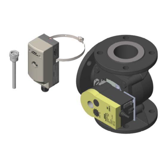
Technische Informationen Maße und Aufbau Abbildung 2 - Aufbau 3-Wege-Umschaltventil (1) Stellantrieb (2) 3-Wege-Umschaltventil (3) Anschlussleitung 230 V AC (4) manuelle Umschaltung (5) Thermostatregler Lieferumfang Im Lieferumfang enthalten: 3-Wege-Umschaltventil Stellantrieb Thermostatregler Spannband für Thermostatregler Einbau- und Bedienungsanleitung K410095501002-00... -
Page 6: Technische Daten
Technische Daten DN 32 – DN 50 DN 65 – DN 80 KTS Temperaturgesteuertes 3-Wege- Ventil Figur 955 01 -Wert [m³ Anschlussgewinde A1 / Rp 1 1/4 Rp 1 1/2 Rp 2 DN 65 DN 80 Flanschanschluss D1 max. Betriebstemperatur [°C] >... -
Page 7: Montage Und Installation
An welchen der mittleren Anschlüsse des Puffer- speichers angeschlossen wird, geht aus dem Hydraulikschema der KTS Trinkwassererwärmungs- anlage hervor. Hinweis: Das Hydraulikschema inkl. der An- schlusssituation 3-Wege-Umschaltventil Abbildung 4 - Anschlusssituation DN 65 - DN 80 ist Teil der Kemper KTS Auslegung K410095501002-00... - Page 8 Hydraulische Einbindung des 3-Wege-Ventils in Verbindung mit einem KTS ThermoTank: Legende: (1) Thermostatregler (2) 3-Wege-Umschaltventil mit Stellantrieb Abbildung 5 - Anlagenschema Primärkreislauf mit einem ThermoTank Achtung: Durchflussrichtung des Ventils beim Einbau beachten! Hydraulische Einbindung des 3-Wege-Ventils in Verbindung mit mehreren KTS ThermoTanks: L egende: (1) Thermostatregler (2) 3-Wege-Umschaltventil...
-
Page 9: Durchflussrichtung Und Installationsanordnung Des 3-Wege-Umschaltventils Dn 32-Dn 50
4.2.2 Durchflussrichtung und Installationsanordnung des 3-Wege-Umschaltventils DN 32 – DN 50 links rechts Einbausituation mit Abgang Einbausituation mit Abgang ThermoTank ThermoTank Mitte Mitte ACHTUNG! Bei E inbaulage rechts muss 3-Wege- Umschaltventil ent- gegen gekenn- zeichneten Fließrich- ThermoTank tung eingesetzt unten werden! ThermoTank unten... - Page 10 Normativer Hinweis: Software Klasse A DIN EN 60730 Verschmutzungsgrad II Typ 1AB Stoßspannungsfestigkeit 4.000 V K410095501002-00...
-
Page 11: Durchflussrichtung Und Installationsanordnung Des 3-Wege-Umschaltventils
4.2.4 Durchflussrichtung und Installationsanordnung des 3-Wege-Umschaltventils DN 65 – DN 80 Einbausituation mit Abgang links Einbausituation mit Abgang rechts Rücklauf ThermoBox Rücklauf ThermoBox ThermoTank ThermoTank Mitte Mitte ThermoTank ThermoTank unten unten 4.2.5 Vorbereitung des 3-Wege-Umschaltventils DN 65 – DN 80 K410095501002-00... - Page 12 Normativer Hinweis: Software Klasse A Verschmutzungsgrad II Kugeldruckprüfung 129 °C DIN EN 60730 Typ 1AB Stoßspannungsfestigkeit 4.000 V K410095501002-00...
-
Page 13: Netzanschluss Und Klemmenbelegungsplan
Netzanschluss und Klemmenbelegungsplan 4.3.1 Anschluss an das Spannungsnetz elektrische Anschluss Warnung: Spannungsnetz (~230 V /50 Hz) ist nach den Der Anschluss an das Span- einschlägigen örtlichen EVU- und den VDE- nungsnetz darf nur durch eine Richtlinien einem Fachhandwerker Elektrofachkraft erfolgen. durchzuführen. -
Page 14: Klemmenbelegungspläne
4.3.2 Klemmenbelegungspläne 4.3.2.1 Stromlaufplan - Anschlusssituation mit Abgang rechts DN 32 DN 40 DN 50 Abbildung 8 - Klemmenplan 3-Wege-Umschaltventil bei Anschluss des ThermoTanks nach rechts K410095501002-00... - Page 15 4.3.2.2 Stromlaufplan - Anschlusssituation mit Abgang links DN 32 DN 40 DN 50 Abbildung 9 - Klemmenplan 3-Wege-Umschaltventil bei Anschluss des ThermoTanks nach links K410095501002-00...
- Page 16 4.3.2.3 Stromlaufplan - Anschlusssituation mit Abgang rechts DN 65 DN 80 Abbildung 10 - Klemmenplan 3-Wege-Umschaltventil bei Anschluss des ThermoTanks nach rechts K410095501002-00...
- Page 17 4.3.2.4 Stromlaufplan - Anschlusssituation mit Abgang links DN 65 DN 80 Abbildung 11 - Klemmenplan 3-Wege-Umschaltventil bei Anschluss des ThermoTanks nach links K410095501002-00...
-
Page 18: Montage Des Thermostatreglers
Montage des Thermostatreglers Der Thermostatregler mit integriertem Anlege- fühler Rückseite möglichst Normativer Hinweis: unmittelbar enganliegend Verschmutzungsgrad II gemeinsamen Primärrücklauf (Rücklauf zwischen ThermoBox(en) und ThermoTank(s)) anzubringen. DIN EN 60730 Hierzu besitzt Thermostatregler Spannband. Dieses ist nach Möglichkeit mit dem Regler in Fließrichtung vor dem 3-Wege- Ventil um die Rohrleitung zu spannen, so dass der Temperaturfühler auf der Rückseite direkt an der Rohrwandung anliegt. - Page 19 55 mm Umgebungst emperatur Typenschild mit Schutzklasse max. 80°C IP 43 Mediumstemperatur Ø Rohr ½“ bis 3“ max. 125°C Schraube lösen Schraube festziehen Fühler bis zum Anschlag ins Tauchrohr stecken K410095501002-00...
-
Page 20: Einstellung Der Umschalttemperatur
Systems führt Fehlfunktionen Beschä- Installation auf Dichtigkeit prüfen. digung Anlagenkompo- nenten. Temperatureinstellung Thermostatregler ϑ vornehmen (Empfehlung KEMPER: 45 °C). Funktionsprüfung des 3-Wege-Umschaltventils durchführen (PWH-Entnahme PWH-C- Hinweis: Betrieb herstellen). Die falsche Einbaurichtung oder Fehlstellung des Ventilkegels in 3-Wege-Umschaltventils führt zum Nicht-Erreichen der... -
Page 21: Wartung Und Instandhaltung
Wartung und Instandhaltung Nach DIN EN 806-5 muss die Trinkwassererwärmungsanlage jährlich gewartet werden. Im Rahmen der Wartung empfiehlt Kemper die folgenden Maßnahmen am 3-Wege-Umschaltventil durchzuführen. Temperaturgesteuertes Mangel / Durchführung Datum 3-Wege-Ventil Beanstandung Thermostatregler auf max. Temp. einstellen Stellantrieb fährt auf Stellantrieb auf Funktion prüfen. - Page 22 Gebr. Kemper GmbH + Co. KG Harkortstr. 5, D-57462 Olpe Tel. +49 2761 891-0 Fax +49 2761 891-175 info@kemper-olpe.de www.kemper-olpe.de K410095501002-00...
- Page 23 Mounting and operating instructions KEMPER KTS temperature-controlled 3-directional reversing valve Figure 955 01 DN 32 – DN 80 Figure 1: DN 32 - DN 50 Figure 1: DN 32 – DN 50 Figure 2: DN 65 - DN 80...
- Page 24 Table of Contents 1 General instructions: ..................1 Operating principle................... 1 2 Safety instructions ..................1 Scope of application: ................2 Mounting location ..................2 3 Technical information ..................2 Dimensions and layout ................2 Scope of delivery ..................2 Technical Data..................
-
Page 25: General Instructions
Attention: Imminent danger 1.1 Operating principle temperature-controlled Normative reference directional reversing valve used combination with the KEMPER ThermoBox and the ThermoTank. Maintenance: task reversing valve Maintenance/Servicing depending on the preset temperature and controller thermostat, redirect return water coming from the ThermoBox into the bottom or middle connection of the ThermoTank. -
Page 26: Scope Of Application
2.1 Scope of application: The 3-directional reversing valve is used solely for the medium of heating plant water. 2.2 Mounting location Install the device solely in frost-free rooms. Ambient temperatures in the mounting location > 55°C are prohibited. The maximum humidity (without condensation) must be <... -
Page 27: Technical Data
3.3 Technical Data DN 32 – DN 50 DN 65 – DN 80 KTS temperature controlled 3-directional valve Figure 955 01 value [m³ Connecting thread A1 / Rp 1 1/4 Rp 1 1/2 Rp 2 DN 65 DN 80 Flange connection D1 Max. -
Page 28: Mounting And Installation
Connection, ThermoTank, middle Note: The hydraulics diagram including the connection situation of the 3-directional reversing valve is part of the Kemper KTS layout Connection, ThermoTank, bottom Figure 6: Connection situation DN 65-DN 80 K410095501002-00... - Page 29 Hydraulic linking of the 3-directional valve in association with one KTS ThermoTank: Legend: (1) Thermostat controller (2) 3-directional reversing valve with servo drive Figure 7: Plant schematic, primary circuit with one ThermoTank Attention: Comply with the direction of flow of the valve when mounting/ installing! Hydraulic linking of the 3-directional valve in association with several KTS ThermoTanks: Legend:...
- Page 30 Direction of flow and installation layout of the 3-directional reversing valve DN 32 – DN 50: Installation situation with outlet left Installation situation with outlet right ThermoTank ThermoTank middle middle ATTENTION! With right-hand installation position, the 3-directional reversing valve must be deployed ThermoTank opposite to the marked direction of flow!
- Page 31 Normative reference: Software category A Pollution class II DIN EN 60730 Type 1AB Surge voltage resistance 4000 V Set servo drive limit to right (100%) Set servo drive limit to left (0%) Plug servo drive Plug servo drive onto the valve onto the valve Rotate lock 45°...
- Page 32 Direction of flow and installation layout of the 3-directional reversing valve DN 65 – DN 80: Installation situation with outlet left Installation situation with outlet right ThermoBox return-flow ThermoBox return-flow ThermoTank ThermoTank middle middle ThermoTank ThermoTank below below Preparation of the 3-directional reversing valve Return-flow, ThermoBox Return-flow, ThermoBox...
- Page 33 Normative reference: Software category A Pollution class II DIN EN 60730 Ball pressure test 129 °C Type 1AB Surge voltage resistance 4000 V Set servodrive limit Set servodrive limit to right (100%) to left (0%) Mount adapter and retaining plate Plug on Plug on servodrive...
-
Page 34: Mains Connection And Terminal Assignment Plan
4.3 Mains connection and terminal assignment plan Connection to the mains supply 4.3.1 Connection to the mains supply Have a skilled tradesmen make the electrical connection to the mains grid (~230 V / 50 Hz) Warning: in accordance with the relevant local power Only trained electricians are utility and VDE directives. - Page 35 Terminal connection plan 4.3.2.1 Circuit diagram - connection situation with outlet right DN 32 DN 40 DN 50 Figure 10: Terminal plan 3-directional reversing valve when the ThermoTank is connected to the right K410095501002-00...
- Page 36 4.3.2.2 Circuit diagram - connection situation with outlet left DN 32 DN 40 DN 50 Figure 11: Terminal plan 3-directional reversing valve when the ThermoTank is connected to the left K410095501002-00...
- Page 37 4.3.2.3 Circuit diagram - connection situation with outlet right DN 65 DN 80 Figure 12: Terminal plan 3-directional reversing valve when the ThermoTank is connected to the right K410095501002-00...
- Page 38 4.3.2.4 Circuit diagram - connection situation with outlet left DN 65 DN 80 Figure 13: Terminal plan 3-directional reversing valve when the ThermoTank is connected to the left K410095501002-00...
-
Page 39: Installation Of Thermostat Controller
4.4 Installation of thermostat controller Attach the thermostat controller with its integrated clip-on bulb on the rear as Normative note: closely and tightly as possible to the Degree of dirt II mutual primary return flow (return-flow between Thermobox(es) DIN EN 60730 ThermoTank(s)). - Page 40 General 55 mm Max. ambient Type plate with temperature 80°C protection rating IP43 Pipe assembly Medium temperature Ø Pipe ½“ to 3“ max. 125°C Assembly of immersion sleeve Tighten the screw Unbolt the screw Push the sensor Fühler bis zum completely into the Anschlag ins immersion sleeve...
-
Page 41: Set Up Of Shift Temperature
(2) Check the installation for leaks. components. (3) Set the temperature on the thermostat controller (KEMPER recommendation: ϑ 45°C). Note: If the installation direction is (4) Make functional... -
Page 42: Maintenance And Repair
Maintenance and repair According to DIN EN 806-5, the drinking water heating system must be maintained annually. Kemper recommends performing the following measures on the 3-directional reversing valve during maintenance. Temperature-controlled Defect / Implementation Date 3-directional valve Complaint Set the thermostat controller to max. - Page 43 Notes: K410095501002-00...
- Page 44 Gebr. Kemper GmbH + Co. KG Harkortstr. 5, D-57462 Olpe Tel. +49 2761 891-0 Fax +49 2761 891-175 info@kemper-olpe.de www.kemper-olpe.de K410095501002-00...
Need help?
Do you have a question about the KTS DN 32 and is the answer not in the manual?
Questions and answers