Table of Contents
Advertisement
Quick Links
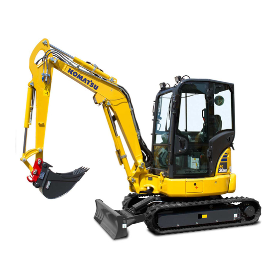
HYDRAULIC
EXCAVATOR
Unsafe use of this machine may cause serious injury or
death. Operators and maintenance personnel must read
this manual before operating or maintaining this machine.
This manual should be kept near the machine for
reference and periodically reviewed by all personnel who
will come into contact with it.
Komatsu has Operation & Maintenance Manuals
written in some other languages. If a foreign language
manual is necessary, contact your local distributor for
availability.
PC45MR
PC55MR
SERIAL NUMBERS
WARNING
NOTICE
TEN00763-04
-5
-5
PC45MR- 30403
PC55MR- 20398
and up
Advertisement
Chapters
Table of Contents


Need help?
Do you have a question about the PC45MR-5 and is the answer not in the manual?
Questions and answers
What are length, thickness and height of blend
The Komatsu PC45MR-5 has the following specifications:
- Overall length of track: 2520 mm (8 ft 3 in)
- Track width (thickness): 400 mm (1 ft 4 in)
- Overall height: 2550 mm (8 ft 4 in) with standard arm, 2590 mm (8 ft 6 in) with long arm.
This answer is automatically generated
PC45MR=5 is switch to ON position, will the machine start?
No, the Komatsu PC45MR-5 will not start when the switch is in the ON position. The ON position allows electric current to flow and enables engine preheating at low temperatures, but to start the engine, the switch must be turned to the START position.
This answer is automatically generated
Where is the fuse bok on PC55
is there a hydraulic piping diagram that i can get