Table of Contents
Advertisement
Quick Links
Operation &
Maintenance Manual
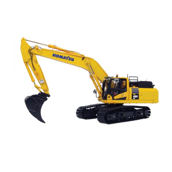
PC490
PC490LC
HYDRAULIC EXCAVATOR
SERIAL NUMBERS
PC490-11
- 85006
PC490LC-11 - 85006
PC490-11
- K70001
PC490LC-11 - K70001
WARNING
Unsafe use of this machine may cause serious injury or
death. Operators and maintenance personnel must read
this manual before operating or maintaining this
machine. This manual should be kept inside the cab for
reference and periodically reviewed by all personnel who
will come into contact with the machine.
-11
-11
and up
and up
and up
and up
ORIGINAL INSTRUCTIONS
UENAM01105
Advertisement
Chapters
Table of Contents


Need help?
Do you have a question about the PC490LC and is the answer not in the manual?
Questions and answers
How to replace an alternator belt
Special tools are required for inspecting and replacing the alternator belt on a Komatsu PC490LC. It is recommended to ask a Komatsu distributor for inspection and replacement. Since an automatic alternator belt tensioner is installed, no belt tension adjustment is needed.
This answer is automatically generated