Narada NPFC Series Operation Manual
Lifepo4 battery module for telecom
Hide thumbs
Also See for NPFC Series:
- Operation manual (44 pages) ,
- Product manual (29 pages) ,
- Operation manual (13 pages)

Related Manuals for Narada NPFC Series


Summary of Contents for Narada NPFC Series
- Page 1 LiFePO Battery Module for Telecom NPFC Series Operation Manual Version: 8.3 NARADA POWER SOURCE CO., LTD...
-
Page 2: Table Of Contents
Table of Contents Part 1 – Safety & Warning ......................1 Part 2 – Product Introduction ......................2 2.1 – Overview ........................2 2.2 – Working Principle ......................2 2.3 – Battery Management System (BMS) ................3 2.4 – Applications ........................3 2.5 –... -
Page 3: Part 1 - Safety & Warning
Part 1 – Safety & Warning Part 1 – Safety & Warning The NPFC series LiFePO battery system installation, operation, maintenance should follow important recommendations in this manual: The equipment shall be installed by the professional training staff ... -
Page 4: Part 2 - Product Introduction
Part 2 – Product Introduction Part 2 – Product Introduction 2.1 – Overview NPFC series battery system is 48V system for communications back-up type LiFePO (lithium iron phosphate) battery products, the system uses the advanced LiFePO battery technology with the benefit of long cycle life, small size, light weight, safety and environmental protection, and has a strong environmental adaptability, it is idea for harsh outdoor environments. -
Page 5: Battery Management System (Bms)
Fe lithium inside system supply DC power to the load, to ensure uninterrupted power supply as power system. 2.3 – Battery Management System (BMS) Smart BMS technology is adopted for battery modules of NPFC series to assure smart automatic management for batteries. Features of BMS are shown as below: ... -
Page 6: Battery Model Instruction
Common Bonding Network (CBN) and or Isolated Bonding Network (IBN) 2.5 – Battery Model Instruction Fig. 2.2 – Instruction of Battery Model for NPFC Series 2.6 – Electric Performance Table 2.1 – Battery Model & Electric Performance of NPFC Series Rated Rated Charge Current (A) Max. -
Page 7: Structure And Mechanical Performance
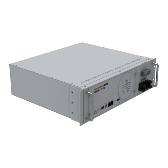
Part 2 – Product Introduction 2.7 – Structure and Mechanical Performance Fig. 2.3 – Structural Drawing of NPFC Series Batteries (48NPFC10 as sample) Fig. 2.4 – Battery Output Terminal Table 2.2 – Mechanical Performance of NPFC Series Dimensions (mm) Battery... - Page 8 Part 2 – Product Introduction Fig. 2.5 – Appearance & Mechanical Drawing of 48NPFC10 Fig. 2.6 Appearance & Mechanical Drawing of 48NPFC20 Fig. 2.7 Appearance & Mechanical Drawing of 48NPFC30 Fig. 2.8 Appearance & Mechanical Drawing of 48NPFC50 LiFePO Battery Module for Telecom Operation Manual V8.3 2016...
- Page 9 Part 2 – Product Introduction Fig. 2.9 Appearance & Mechanical Drawing of 48NPFC70 Fig. 2.10 Appearance & Mechanical Drawing of 48NPFC80 LiFePO Battery Module for Telecom Operation Manual V8.3 2016...
-
Page 10: Part 3 - Technical Characteristics
Part 3 – Technical Characteristics 3.1 – Discharge Performance Fig. 3.1 – Constant Current Discharge Curve of NPFC Series 3.2 – Charge Performance Fig. 3.2 – Charge Characteristic with Various Current Limitation of NPFC Series LiFePO Battery Module for Telecom Operation Manual V8.3 2016... -
Page 11: Constant Current/Power Discharge Datasheet
Part 4 – Operation & Maintenance 3.3 – Constant Power Discharge @77F/25C 48VNPFC10 Constant power discharge End voltage 10hr 3.5hr 2.5hr 1.5hr 46.5V 49.0 60.0 96.0 45.0V 49.9 61.4 98.2 43.5V 50.5 62.1 99.4 42.0V 50.9 62.5 40.5V 51.1 62.9 39.0V 51.2 63.0... - Page 12 Part 4 – Operation & Maintenance 48VNPFC70 Constant power discharge End voltage 10hr 3.5hr 2.5hr 1.5hr 343.1 46.5V 428.9 672.2 1541 1979 2708 349.4 45.0V 436.8 687.2 1634 2147 3118 353.4 43.5V 441.7 695.6 1669 2185 3212 356.0 42.0V 445.0 1681 2222 3268...
- Page 13 Part 4 – Operation & Maintenance 48NPFC30 Constant Current discharge 10hr 3.5hr 2.5hr 1.5hr Voltage 46.5 10.6 12.6 16.7 20.7 45.0 11.5 14.1 20.2 26.3 44.1 11.7 14.4 20.8 27.1 43.5 11.8 14.6 21.2 27.8 42.0 11.9 14.8 21.7 28.5 40.5 12.0 14.9...
-
Page 14: Part 4 - Operation & Maintenance
5% ~ 95% 4.2 – Parameter Settings of Power Plant Lead-acid batteries can be replaced by lithium battery of NPFC series if power is matched. Table 4.2 is new parameter settings of power plant for lithium battery. Table 4.2 – Parameter Settings of Power Plant for NPFC Series Batteries... -
Page 15: Layout Of Front Panel
Part 4 – Operation & Maintenance 4.3 – Layout of Front Panel Fig. 4.1 – Layout of Front Panel for NPFC Series Batteries Fig. 4.2 – Layout of Right Side Panel for NPFC Series Batteries Table 4.3 – Instruction for Layout of Front Panel Marks... -
Page 16: Installation
Part 4 – Operation & Maintenance 1200bps. RS232 up-link communication can be available for the battery module with a binary communication address of 0000 (Master PACK). Protocol for RS232 communication is shown in Annexed Table 3.1 It is adopting RS485 series port communication pattern to Cascading upload data. -
Page 17: Preparation For Installation
Laptop Operate the software 4.4.3 – Installation of Battery Modules 1) Installation and fixation Battery modules of NPFC series are applicable to installation in 19inches cabinets and wall-hanging. 19inch cabinet installation Insert battery module into 19 inch cabinet, and fix two handles of battery module with cabinet rack using 4pcs M6 screws. - Page 18 Color for cable between ‘+’ and positive bar is suggested as BLACK, and cable between ‘-’ and negative or breaker as BLUE. Fig. 4.3 – Layout of paralleling connection for NPFC Series Batteries 4) Power on for battery module When installation is accomplished, battery module is in dormant state. Once power on ...
-
Page 19: Maintenance
Part 4 – Operation & Maintenance be available using RS485. Communication protocols for RS232 and RS485 are shown in Annex 3. 6) Discharge with dummy load Dummy load cannot be larger maximum discharge current of each battery model in ... -
Page 20: Part 5 - Troubleshooting & Solutions
Annex 1 – Instructions for LED Flicker Part 5 – Troubleshooting & Solutions Table 6.1 – Troubleshooting and Solutions Troubles Troubleshooting Solutions Protection against under-voltage Charge battery Protection against over-temperature Regulate ambient temperature in the under-temperature (Ambient temperature is lower range of -20℃... -
Page 21: Annex 1 - Instructions For Led Flicker
Annex 2 – Instructions for Dialing of ADD Annex 1 – Instructions for LED Flash Annex Table 1.1 – SOC LED Indicators Description ● ● ● ● ☼ ☼ ☼ ☼ 75% ~ 100% ☼ ☼ ☼ ○ 50% ~ 75% ☼... -
Page 22: Annex 2 - Instructions For Dialing Of Add
Annex 2 – Instructions for Dialing of ADD Annex 2 – Instructions for Dialing of ADD ADD is applicable to modules connected in parallel. ADD consists of four binary bits, and maximum quantity of batteries connected in parallel is 16pcs (2^4). Annexed Table 2.1 –... -
Page 23: Annex 3 - Communication Protocol For Rs232 And Rs485
Annex 3 – Communication Protocol for RS232 and RS485 Annex 3 – Communication Protocol for RS232 and RS485 There is one RS232 port in front panel for up-link communication between batter module and upper computer, and one RS485 port in front panel for cascade communication for battery modules connected in parallel. - Page 24 Annex 3 – Communication Protocol for RS232 and RS485 Annex 4 – LCD Menu Instruction Press “MENU” to enter the following interface Welcome Battery manage system ------------------------- Press “MENU” next Press “MENU” to enter the following interface Battery parameters query Battery status Battery parameter settings Version Information...
- Page 25 Annex 3 – Communication Protocol for RS232 and RS485 ——Cell13: xxxx mV ——Cell14: xxxx mV ——Cell15: xxxx mV ——Cell16: xxxx mV ——SOC: xxxx% ——Nominal Capacity: xxxx Ah ——Remaining Capacity: xxxx Ah ——Battery Cycles: xxxx The “Battery Status” Subdirectory ——Status: IDLE/CHARGE/DISCHARGE ——the “alarm status”...
-
Page 26: Annex 4 -Lcd Menu Instruction
Annex 3 – Communication Protocol for RS232 and RS485 ——under voltage times: xxxx The “Battery parameter settings” Subdirectory Non-manufacturers cannot enter 10 NPFC series LiFePO Battery System for Telecommunication Operation manual V1.0 The “Version Information” Subdirectory ——the “BMS version” Subdirectory ——BMS software version...
Need help?
Do you have a question about the NPFC Series and is the answer not in the manual?
Questions and answers
Sunsynk 5.5 inverter and NARADA NPFC 100 BMS is not working. I used the RS458 port with protocal 16 and dip switch 1 on battery is on. still not working. Please advise