
Related Manuals for DigiTech QM-1552


Summary of Contents for DigiTech QM-1552
- Page 1 QM-1552 True RMS Inductance SPECIALIST /Capacitance Digital Multimeter User Manual...
- Page 2 QM-1552 True RMS Inductance /Capacitance Digital Multimeter User Manual Thank you for purchasing this Digital Multimeter. A powerful true RMS multimeter that includes non-contact voltage testing, and a backlit LCD. Please familiarise yourself with the functions of the multimeter before use.
- Page 3 FUNCTIONS Max. Display 2000 Counts Basic Accuracy 0.5% DC Voltage Range 200mV-1000V AC Voltage Range 200mV-750V DC Current Range 200µA-10A AC Current Range 200µA-10A Resistance(Ω) 200Ω>200MΩ Capacitance (CAP) 10nF-100mF Frequency (Hz) 10Hz-10MHz Inductance 2mH-20H Temperature -20°C - 1000°C Data Hold Diode Test Duty Cycle Continuity Check...
- Page 4 SAFETY This symbol indicates that the operator must refer to an explanation in the Operating Instructions to avoid personal injury or damage to the meter. CAUTIONS • Improper use of this meter can cause damage, shock, injury or death. Read and understand this user manual before operating the meter. •...
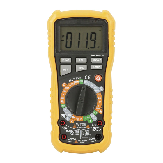
- Page 5 LED Indicator LCD Display Function Buttons Rotary Switch Input Jacks...
- Page 6 FUNCTIONS LCD Screen Readings and measurements taken by the multimeter will display in this area. Function HOLD: Press this button to lock the readings in the LCD, Buttons press again to exit the hold mode. Press “ ” to switch the back light mode, around 15 second exit from back light mode.
- Page 7 SYMBOL DESCRIPTION HOLD Data Hold Diode Test Unit of Voltage Unit of Frequency Ω Unit of Resistance KΩ MΩ Transistor TRMS True RMS Measurement Duty Cycle Measurement Low Voltage Indication Continuity Check Unit of Current Unit of Capacitance Unit of Inductance °C Centigrade Temperature °F...
-
Page 8: Box Contents
GENERAL SPECIFCATIONS Max. Input Voltage: AC750VRMS, DC1000V Sampling Rate: Approx. 2 times/sec Operating Temperature: 0°C-40°C (32°F~104°F) Operating Humidity: <80%RH Storage Temperature: -10°C-60°C (14°F~122°F) Storage Humidity: <70%RH Power Supply: 9V Battery (6F22) x 1pc Dimension: 200 x 92 x 60mm (L x W x H) Weight: Approx. - Page 9 DC VOLTAGE RANGE RESOLUTION ACCURACY 200mV 0.1mV ±(0.5% reading + 3 digits) 0.001V 0.01V ±(0.8% reading + 3 digits) 200V 0.1V 1000V ±(1.0% reading + 5 digits) Input Impedence: 10MΩ Max. Input Voltage: 1000VDC AC VOLTAGE RANGE RESOLUTION ACCURACY 200mV 0.1mV 0.001V ±(1.0% reading + 5 digits)
- Page 10 AC CURRENT RANGE RESOLUTION ACCURACY 200µA 0.1µA ±(1.2% reading + 5 digits) 0.001mA 20mA 0.01mA ±(1.5% reading + 5 digits) 200mA 0.1mA 0.001A ±(1.8% reading + 15 digits) 0.01mA Overload Protection: Fuse FF200mA/500V for mA range Fuse FF10A/500V for A range Frequency Range: 40-1000Hz RESISTANCE...
- Page 11 TEMPERATURE RANGE RESOLUTION ACCURACY -20° ~ 400° 1°C ±(2.0% reading + 3 digits) 400° ~ 1000° 0° ~ 752° 1°F ±(3.0% reading + 3 digits) 752° ~ 1832° Overload Protection: 250VDC or 250VAC RMS FREQUENCY RANGE RESOLUTION ACCURACY 10Hz 0.01Hz 100Hz 0.1Hz 1kHz...
- Page 12 CAPACITANCE RANGE RESOLUTION ACCURACY 10nF 0.001nF ±(4.0% reading + 25 digits) 100nF 0.01nF 1µF 0.001µF ±(4.0% reading + 25 digits) 10µF 0.01µF 100µF 0.1µF 1µF 10mF 10µF ±(5.0% reading + 25 digits) 100mF 100µF Overload Protection: 250VDC or 250VAC RMS NOTE: It is normal for small capacitance measurements to display a reading once removed from the component being measured.
- Page 13 • To avoid electrical shock and/or damage to the instrument, do not attempt to take any voltage measurement that might exceed 1000VDC or 750VAC RMS. • To avoid electrical shock and/or damage to the instrument, do not apply more than 1000VDC or 750VAC RMS between the common terminal and the earth ground.
- Page 14 NOTE: • In a circuit, a good diode should produce a forward bias reading of voltage, however, the reverse-bias reading can be variable based on resistance of other pathways between the probe tips. • To avoid electric shock, never measure continuity on circuits of wires with voltage.
-
Page 15: Inductance Measurement
NOTE: • The test may take more time for large capacitors to charge, wait until the readings settle before removing the leads. • To improve the accuracy of measurement less than 10nF, subtract the residual capacitance of the meter and test leads. TEMPERATURE MEASUREMENT WARNING: To avoid electrical shock, do not perform temperature measurement when... -
Page 16: Hold Function
HOLD FUNCTION The hold function freezes the reading in the display, press the HOLD button momentarily to activate or to exit the hold function. AUTO POWER OFF The auto off feature will turn the meter off after 15 minutes. LOW BATTERY INDICATION icon will appear in the LCD display when the battery voltage becomes low, replace the battery when this icon appears.
Need help?
Do you have a question about the QM-1552 and is the answer not in the manual?
Questions and answers