Advertisement
MR5 | MR6
CONNECTIONS SCHEME
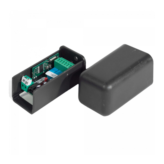
The MR5 – MR6 dual channel radio receiver allows to control electric and electronic devices when
coupled with one or more transmitters.
Antenna
CH2
LED
DIPPERS
ATTENTION!
Pay attention to the
jumper position
1
2
before connecting to
power
12/
0V
24
12 or 24V
Power supply
Unifilar
hard wire
antenna
7
8
CH1
LED
ON
SEL
BOTTON
1
2
JUMPER
3
4
5
6
CH1
CH2
Start 2
NO
Start 1
NO
TECHNICAL SPECIFICATIONS
• CONNECTOR'S DESCRIPTION
01 • 12-24V AC/DC Power supply
02 • 0V Power supply
03 • CH1 contact output - NO
04 • CH1 contact output - NO
05 • CH2 Contact output - NO
06 • CH2 Contact output - NO
07 • Antenna mass input
08 • Antenna hot pole input
• CHARACTERISTICS BOARD
• Frequency
• Power supply
• Maximum consumption
• Code type
• Code memorization (CH1 + CH2)
• Relay
• Temperature
• Dimensions
• Range in open space
• Protection Grade
• JUMPERS
By selecting Jumper J1 position, you can select the power supply voltage:
POSITION
Pos. 1-2
12V AC/DC.
Pos. 2-3
24V AC/DC (from factory).
433,92 MHz
12-24V AC/DC
5W
12-18-32 Bit or Rolling Code
500 Max
30V DC 1A
-10°C to 55°C
53x82x40mm
50-100m
MR5 - IP 42 | MR6 - IP 54
VOLTAGE
EN
Advertisement
Table of Contents

Summary of Contents for Motorline MR5
- Page 1 CONNECTIONS SCHEME TECHNICAL SPECIFICATIONS • CONNECTOR’S DESCRIPTION The MR5 – MR6 dual channel radio receiver allows to control electric and electronic devices when coupled with one or more transmitters. 01 • 12-24V AC/DC Power supply 02 • 0V Power supply 03 •...
- Page 2 The receiver is provided with a local antenna. If you choose an external antenna (for MR5), it should be positioned on the outside, in highly visible spots and away from metal structures.


Need help?
Do you have a question about the MR5 and is the answer not in the manual?
Questions and answers