Table of Contents
Advertisement
Quick Links
Advertisement
Table of Contents

Related Manuals for CUOGHI MININEB


Summary of Contents for CUOGHI MININEB
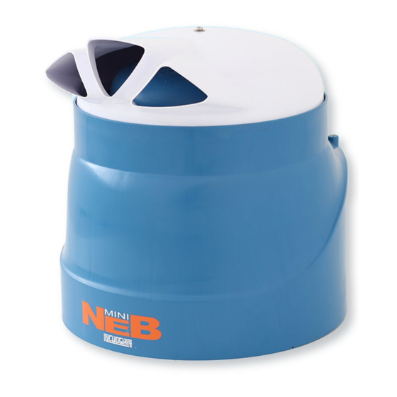
- Page 1 Adiabatic humidifier...
-
Page 3: Technical Features
1. Technical features 1.1. Technical data table Atomization Capacity Atomization Capacity Atomization Capacity Atomization Capacity 2.6 lbs/hour Power Supply Power Supply Power Supply Power Supply 120 V, 60 Hz Nominal Current Nominal Current Nominal Current Nominal Current 0.12 A Air Flow Air Flow 52 cfm Air Flow... -
Page 5: Installation
The installation must comply with local safety regulations. 3.2. Positioning The MININEB must be fitted as in Pic. 3.2.1, Pic. 3.2.2, Pic. 3.2.3, in horizontal position, with the air filter directioned below, leaving a correct space from the ground. Any other positioning compromizes the correct performance of the machine. - Page 6 3.3. Electrical connections 3.3.1. Electrical wiring diagram 1 1 1 1 Humidifier motor 2 2 2 2 Floating switch 3 3 3 3 Solenoid Valve 4 4 4 4 External Humidistat Bridge External Humidistat 120 V, A A A A 60 Hz, 0.2 A (Not supplied) Line Protection (Not B B B B...
-
Page 7: Hydraulic Connections
The water supply hose A has a threaded bush G ¾ on both ends. Connect the L-shaped end to the solenoid valve of the MININEB, and the other end (the straight one) directly to a tap (B) or an extention. It’s suggested... - Page 8 • Drill three ¼ inch diameter holes about 1 1/4 inches deep on the wall, as in Pic. 3.5.2; • Clean the holes internally. • Insert the three screw anchors keeping the espansion fins on the vertical plane; fasten the bracket with the three screws. •...
-
Page 9: Maintenance
4. Startup, control and switch off. 4.1. Checks Before starting the humidifier, check the following points: • All connections, both electrical and hydraulic, must be made as is written in the present manual. • There must be no water dripping in the circuit. •... -
Page 10: Air Filter Cleaning
5.2. Air filter cleaning Pic..5.2 5.2..1 1 1 1 – – – – Air filter disassemble Air filter disassemble Air filter disassemble Air filter disassemble The air filter must be periodically cleaned, as the continuous accumulation of dirt and dust progressively reduce the air flow, and consequently affect the efficiency of the machine. -
Page 11: General Notes
5.3. Inspection and Cleaning of the Discharge Siphon It may be necessary to clean periodically the water discharge siphon R (see: Pic. 5.3.1) as the accumulation of dirt inside may compromise its correct and efficient operation. When a cleaning is necessary, see the following steps: •... -
Page 12: Product Disposal
6.3. Product disposal The machine is mainly composed of plastic components, and some metal parts, both recyclable. Before disposing of it, separate the plastic parts (body, cover, grille, etc.) from the metal ones (motor bracket, wall installation bracket, etc.). Remove the electrical cabling and dispose of it as by standard regulations 7.
Need help?
Do you have a question about the MININEB and is the answer not in the manual?
Questions and answers