
Summary of Contents for IGEBA EVO 35
- Page 1 EVO 35 - EVO 35 E Справочное руководство Instruction manua Термомеханические аэрозольные генераторы...
-
Page 2: Table Of Contents
Cleaning the mixing chamber/mixing pipe…………………………………….. 40 - 42 Maintenance of the pump……………… 42 Fault finding……………………………… 43 - 52 EVO 35 E Functional parts EVO 35 E………………53 - 54 Operation with Emergency-Cut-Off- device………………………………….. Adjustment of the Bowden cable……… 56 Basic setting Emergency-Cut-Off- device………………………………….. -
Page 3: Evo 35
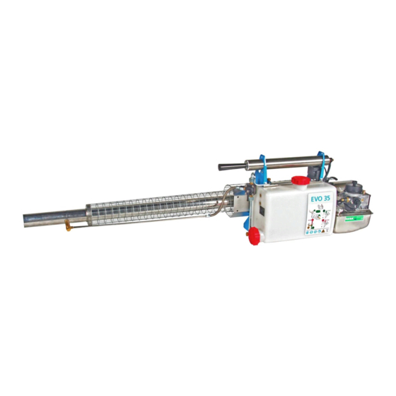
EVO 35 The important functional parts of EVO 35 at a glance / Notice: Solution tap positions – Open – Closed - Ventilation 04/2010... - Page 4 6. It is forbidden to fog in rooms with finest combustible dust particles (e.g. grain silo), because danger of dust explosion. . .). 7. It is forbidden to fog in enclosed rooms where open flames, candle lights, hot engines or electrical appliances exist, because of fire danger.
-
Page 5: Prepare Unit Ready For Use
1. Prepare unit ready for use: Due to packing reasons, the fog tube is not mounted on the unit. The standard fog tube (illus. 1 pos.9) must be used for oil based formulations. The fog tube type W (iIllus.1 . 1, . - Page 6 . 2, Fit the protective guard (illus. 2 pos.11) to .11) the end of the cooling jacket and tighten clamp. illus. 2 . 68 SP list page 68 Push fog tube (illus.3 pos.9) over the . 9) resonator into the cooling jacket until the hole is aligned (illus.3a pos.9) with the screw neck to screw in the fog solution .
- Page 7 Screw in the fog solution socket by hand . 4). (illus. 4). Connect fog solution socket and solution line via the dosage nozzle and related copper gaskets (illus.5). When tightening the dosage nozzle secure the position of the fog solution socket with a second flat spanner (illus.5).
- Page 8 Inserting the batteries: йки: Remove the upper wing thumb screw completely. It is sufficient to loosen the lower thumb screw a few revolutions. You can take off the battery cover now (see note). Insert four batteries Type 1,5V LR20 with the positive pole forward inside the LR20 unit.
- Page 9 Fill petrol tank with petrol > 75 ROZ, > 75. without additives. There advantage achieved in using higher grade е petrol. Please use the provided funnel with strainer (illus. 8 pos. 2). After filling, tighten petrol cap firmly by hand. .
- Page 10 SP list page 71 . 71 Solution output through Dosage Nozzles EVO 35 EVO 35 is already equipped with a dosage nozzle size of 1.2. A Nozzle with size 0.8 is 1.2. in the scope of supply. 0.8. EVO 35 W Another nozzle with size 1.0 is in the scope...
- Page 11 The output (liter/hour) differs up to 20% due to the different chemical and physical properties of the formulations. We advise 20%. you to do your own metering of the output under prevailing conditions. This refers mainly to tropical countries. . Э When applying water based formulations use a small dosage nozzle size max.
-
Page 12: Starting The Unit
2. Starting the unit: Pull stop button at the carburettor upwards . 11, . 1) (illus. 11 pos.1). Press starter button (for ignition) and keep . 11, pressed (illus 11 pos.2). . 2). Actuate air pump . Pump evenly, (illus. 11 pos.3) not fitfully. -
Page 13: Stopping The Unit
. 12 illus. 12 SP list page 70 . 70 – Open – Closed - Ventilation Important! Make sure that the amount of petrol is sufficient for the intended period of fogging. The content of the standard solution tank is 6,5- 6,5 liter, which is fogged according to the size of the dosage nozzle between 8 and... -
Page 14: Cleaning The Unit
3–4 Explosions of remaining gases might be audible (illus. 11 page 34). ки а Release pressure from solution tank by . 11, . 34). turning tank cap to the left. Attention! Do not tighten tank cap hard during storage of the unit. . - Page 15 . 14 illus 14. . 14a illus. 14a. . 65 SP list page 65 При и By using dirty petrol cans or polluted petrol, debris may be piled up inside the petrol tank. This debris can be removed of the tank by filling up a quarter liter of 0,25 gasoline.
- Page 16 We recommend before longer periods of storage: a.) Remove batteries from the unit and store them at a safe and dry place. b.) Remove solution from the solution tank and clean as stated above. (illus. 14 page 37 ) Do not tighten tank cap hard. 37);...
- Page 17 e.) Remove residues in resonator, fog - solution socket and possibly fog tube with pipe cleaning tool (illus.17, pos.3). . 17, . 3). . 17 illus. 17 . 68-70 SP list page 68-70 04/2010...
-
Page 18: Pipe
5. Ч 5.Cleaning from the mixing chamber and mixing pipe. a) отсоедините контактный наконечник от плунжера a.) Remove the plug from the swirl vane (illus. 18 pos.2). . 18,поз. 2). . 18 illus. 18 . 69 SP list page 69 . - Page 19 . 19 illus. 19 . 69 SP list page 69 c.) Clean the inside of the mixing chamber and mixing pipe. Remove combustion residues with pipe cleaning tool. When inserting the pipe cleaning tool into the mixing chamber pay special attention to the atomizer nozzle which enters the .
-
Page 20: Maintenance Of The Pump
The O-Ring has to be placed like shown in iIlus.20 pos.21 in the carburettor housing. . 20, . 21. . 20 illus 20. . 69 SP list page 69 Maintenance of the pump: • The maintenance of the pump has to be performed one or two times per year. -
Page 21: Fault Finding
6. Fault finding: a) Unit does not work properly anymore: If the unit has run for some time and will not start or does not run properly any more, it might be due to the following: Air intake valve is dirty (illus. 15+16 ... - Page 22 b.) Unit does not work after initial start If the unit does not run properly after the initial start, the following steps should be considered: Every unit is checked before delivery. It must be taken into consideration that our factory is located approx. 800 m above sea- level, the average temperature in our test room is 15°...
- Page 23 • “Flooding”: When starting the warm unit, it is possible due to vigorous pumping that the carburettor floods (Device stops). In this case, petrol fumes emerge at the end of the fog tube. Push down the stop button (illus.11 page 34) to STOP „STOP“...
- Page 24 . 23 . 71 illus.23 SP list page 71 3.) Check whether the contact spring, the wing screw and the support are well connected with each other. Clean the contact surfaces if contact surfaces are . 24, . 16). covered with dirt or rust. (illus 24 pos.16).
- Page 25 . 24a illus. 24a. . 64 SP list page 64 • ● Unscrew regulating needle (illus. 25 . 1) pos.1), actuate air pump, petrol should, emerge, absorb alternatively swab про emerging petrol. Fire hazard: keep off ignition sources. If there is no fuel emerging: .
- Page 26 • ● Remove petrol suction line, thereto unscrew the carburator (illus26 pos.9) from . 26, . 9) the gasoline tank and from the resonator (illus. 26 and page 48 illus. 27). Check felt . 26 и 27, . 48). tube for dirt and replace it if necessary (illus.28 page 48).
- Page 27 • • Unscrew the cap by turning it counter- clockwise (1.) and pull the complete pump (2). spindle out of the pump tube afterwards. • • Check collar (illus. 29 pos. 2.4) of pump . 29, . 2.4) , spindle for proper position and replace if damaged.
- Page 28 • • Clean mixing chamber with pipe cleaning . 20, tool (illus. 20 page 42). 42). • • Unscrew fog solution socket, remove residues from resonator end and fog tube with the pipe cleaning tool (illus. 17 page . 17, 39).
- Page 29 • • Check if tank cap of solution tank is airtight, replace gasket if necessary. • • Check if the boreholes of the double hollow scew are blocked, if so, pierce them . 31, . 5). with a fine wire (illus. 31 pos. 5). .
- Page 30 . 32 illus.32 . 69 SP list page 69 04/2010...
-
Page 31: Functional Parts Evo 35 E
04/2010... - Page 32 04/2010...
-
Page 33: Device
04/2010... -
Page 34: Adjustment Of The Bowden Cable
04/2010... -
Page 35: Device
04/2010... - Page 36 04/2010...
-
Page 37: Technical Data
04/2010... - Page 38 04/2010...
-
Page 39: Manufafcturing Programm
04/2010... -
Page 40: Spare Parts List
04/2010...
Need help?
Do you have a question about the EVO 35 and is the answer not in the manual?
Questions and answers