Advertisement
Quick Links
2
A
Note: Refer to the C52 Owner's Manual page 9 for additional connection information.
Connection Legend:
Data Cable*-
Digital Signal Cable -
Sensor/Keypad Cable -
RS232 Cable -
Power Control Cable* -
Ground Wire -
Audio Signal Cable -
AC Power Cords -
Video Signal Cable -
Loudspeaker Cable -
RF Signal Cable -
*
2 conductor shielded with 1/8 inch stereo mini phone plug on each end.
Power Amplifier (Right Channel) - Main Room
(Partial View)
Power Amplifier (Left- Channel) - Main Room
(Partial View)
McIntosh Laboratory, Inc. 2 Chambers Street Binghamton, New York 13903-2699 Phone: 607-723-3512 FAX: 607-724-0549
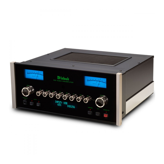
C52 Audio Preamplifier Passthru Connection Diagram
Connect to
AC Outlet
Part No. 04157600
A/V Processor
Advertisement

Summary of Contents for McIntosh C52
- Page 1 C52 Audio Preamplifier Passthru Connection Diagram Note: Refer to the C52 Owner’s Manual page 9 for additional connection information. A/V Processor Connection Legend: Data Cable*- Digital Signal Cable - Sensor/Keypad Cable - RS232 Cable - Power Control Cable* - Ground Wire -...
- Page 2 C52 to determine the when the C52 is switched On/Off control device with the C52 Remote Control Transport Components a digital audio signal correct voltage for your unit McIntosh Laboratory, Inc. 2 Chambers Street Binghamton, New York 13903-2699 Phone: 607-723-3512 FAX: 607-724-0549...


Need help?
Do you have a question about the C52 and is the answer not in the manual?
Questions and answers