
Related Manuals for McIntosh C52


Summary of Contents for McIntosh C52
- Page 1 McIntosh Laboratory, Inc. 2 Chambers Street Binghamton, New York 13903-2699 Phone: 607-723-3512 www.mcintoshlabs.com Audio Preamplifier Owner’s Manual...
-
Page 2: Safety Instructions
he lightning flash with arrowhead, within an equilateral triangle, The exclamation point within an equilateral triangle is intended to is intended to alert the user to the presence of uninsulated “dan- alert the user to the presence of important operating and mainte- gerous voltage”... -
Page 3: Table Of Contents
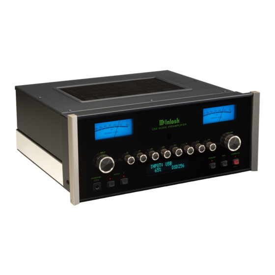
Thank You Customer Service Front Panel: Your decision to own this McIntosh C52 Audio Pre- If it is determined that your McIntosh product is in amplifier ranks you at the very top among discrimi- need of repair, you can return it to your Dealer. You Front Panel Displays, Controls, Push-buttons and Jack .............. -
Page 4: General Information
McIntosh Power Amplifiers. A to the C52 Audio Preamplifier. ponents. For additional information go to www. 3.5mm stereo mini phone plug is Power 2. The Main AC Power going to the C52 and any mcintoshlabs.com. used for connection to the Power Control Meter other McIntosh Component(s) should not be applied 8. -
Page 5: Introduction
Stainless Steel Chassis with Super Mirror decodes SACD/CD signals from an external Trans- The Front Panel Information Display indicates the Finish ensures the pristine beauty of the C52 will be port component. The USB Input for streaming audio Source Selection, Volume/Balance Levels and Setup retained for many years. -
Page 6: Dimensions
Dimensions Dimensions The following dimensions can assist in determining the best location for your C52. There is additional information on the next page pertaining to installing the C52 into cabinets. Front View of the C52 " 44.5cm " " Side View of the C52 19.4cm... -
Page 7: Installation
Installation Installation " 3/16 The C52 can be placed upright on a table or shelf, 43.66cm standing on its four feet. It also can be custom in- stalled in a piece of furniture or cabinet of your choice. The four feet may be removed from the bottom of the C52 when it is custom installed as outlined be- low. -
Page 8: Connections
C52 Remote Control HR085. With an external sensor connected to the C52, remote control operation of the system is possible from another room and/or when the C52 is located in a cabinet with the doors closed. The connection instructions below, together with the C52 Input/Output/Control Connection Diagrams located on the separate folded sheets “Mc1A/1B and... -
Page 9: Connections
18. Connect the Audio Cables coming from the Turn- Data Control Connections: 26. Connect the C52 to a live AC Outlet using the sup- table to the C52 MC PHONO INPUT Jacks. 9. Connect a Control Cable from the C52 DATA plied Power Supply Cord. -
Page 10: Hr085 Remote Control Push-Buttons
Tuner scans Up the dial to for the next selection SEEK the next Station Selects Previous Tuner Station PRESET Tuner scans Down the dial to SEEK the next Station Note: Push-buttons whose function is not identified above are for use with other McIntosh Products. -
Page 11: How To Use The Hr085 Remote Control
McIntosh Source Components connected to the C52 via the Data Ports. Notes: 1. If at any time the C52 seems unresponsive to the HR085 Remote Control Commands, press DEVICE Push-button to select first. -
Page 12: Front Panel Displays, Controls, Push-Buttons And Jack
OUTPUT 1 and 2 Push-buttons EQUALIZER Push-button with indicator, STANDBY/ON Push-button with indicators, switch the when de-activated the audio signal bypasses with indicator, switches the C52 Preamplifier Outputs 1 and 2 the Equalizer Controls ON or OFF (Standby) and resets On or Off... -
Page 13: Setup
Default Settings PUTS Off (or back On if they have been previously Note: If the C52 is currently On, proceed to step 2. The Default Settings Chart below indicates the Func- switched Off). The default INPUT Names can be 1. -
Page 14: Rename Input
< nent connected (refer to page 9, step 15). the character “B” to “M”. Refer to figure 9. The C52 Default Input Names (UNBAL 1, BAL 1, Figure 13 COAX 1, etc.) as indicated on the Front Panel Dis- RENAME: BAL 1... -
Page 15: Output Settings
Setup, con’t Output Settings The Output Settings provide the ability to change how SETUP: OUTPUT 2 RENAME: BAL 1 the C52 Output 1, Output 2 and Headphones function. Switched >MEDIA < OUTPUT 1 and 2: Figure 24 Figure 15 By defaut OUTPUT 1 and 2 are set to go On/Off by... -
Page 16: Power Control Triggers 1 And 2
McIntosh Source Component allows for basic func- Output 2 is selected. TRIGger 3 and TRIGger 4 are assigned to tion control of the source component using the C52 function the same as the MAIN Power Control Jack, supplied HR085 Remote Control. By default, all of... -
Page 17: Passthru
Decoder can “Passthru” the C52 and onto its associ- from 9,600 bits per second to 115,200 bits per second. are used when the C52 is used in the same location as ated Power Amplifier(s). The Setup Mode allows To change from the default speed of 115,200 bits per another McIntosh Preamplifier and/or A/V Processor. -
Page 18: Operation
IR Sensor Power Mode Factory Reset The C52 Front Panel Sensor, which receives the sig- The C52 incorporates an Auto Off Feature, which If it becomes desirable to reset all the adjustable set- nals from the HR085 Remote Control, can be switched... - Page 19 Notes...
-
Page 20: How To Operate The C52
Rotate the Front Panel VOLUME Control or use the Note: Selection and Adjustment of figures 60, 61, 62 and 63. To switch OFF the C52 press all Trim Functions may be the STANDBY/ON Push-button on the Front Panel or... - Page 21 Control when switching between different sources. LEVEL. Refer to figure 73. 2. Select “MONO / STEREO, The C52 allows the adjustment of levels for each of the indicated on the Front Panel Information Display. EQUALIZER Source Inputs for the same relative volume. To adjust Refer to figure 70.
- Page 22 Notes: 1. Meter Illumination of recent McIntosh Power BRIGHTNESS Amplifiers will also switch On/Off when con- METER ILLUMINATION nected to the C52 via a power control cable. The C52 Front Panel Meter Illumination may be Figure 77 2. Some A/V Processors will provide an On/Off...
- Page 23 MUTE in place of the actual volume setting. shows the range of adjustment of frequencies for each Refer to figure 80. of the Equalizer Controls of the C52 at the +6dB and -6dB points. INPUT: BAL 1 MUTE...
- Page 24 The default setting is for all BARITONE of the Power Amplifier Output Connections (Main, 1, BASS 2, and 3) to automatically mute. When headphones are connected to the C52 Front PICCOLO Panel Jack, an additional TRIM function becomes FLUTE available. McIntosh’s HXD brings the acoustical...
-
Page 25: Optical And Digital Inputs
McIntosh Web Site: When a Digital Input (Optical or Coxial Connection) http://www.mcintoshlabs.com/us/Support/Pages/ Manuals.aspx on the C52 is selected, the Front Panel Information Under “PRODUCT CATEGORY” select “Pre- Display indicates the sampling frequency when a amplifiers” then under “MODEL NUMBER” select signal is present. - Page 26 Computer USB Connection, it is required to make ures 103 and 104. changes to Windows Sound Settings: Notes: 1. It is not necessary for the McIntosh-HD USB 1. From the Windows Audio Control Panel to be running, unless it is START button, click on desired to make changes to the default settings.
-
Page 27: Usb Music Playback
2. To switch the C52 back On, press the STANDBY/ or 256 times the Sampling Rate of a CD Disc for the ON Push-button. Note: This can be performed with the C52 On or in the incoming DSD Digital Audio Signal. Standby Mode. -
Page 29: Photos
Photos... -
Page 30: Specifications
Phono MM, 50mV Standby Power, less than 0.5 watts Maximum Voltage Output Phono MC, 5mV Note: Refer to the rear panel of the C52 for the correct 8V RMS Unbalanced, 16V RMS Balanced voltage. Voltage Gain Sensitivity (for rated output) -
Page 31: Packing Instruction
Customer Service Depart- 404080 #10-7/16” Flat washer ment of McIntosh Laboratory. Refer to page 3. Please see the Part List for the correct part numbers. - Page 32 McIntosh Laboratory, Inc. 2 Chambers Street Binghamton, NY 13903 www.mcintoshlabs.com The continuous improvement of its products is the policy of McIntosh Laboratory Incorporated who reserve the right to improve design without notice. Printed in the U.S.A. McIntosh Part No. 04157800...
Need help?
Do you have a question about the C52 and is the answer not in the manual?
Questions and answers