Table of Contents
Advertisement
Quick Links
Instruction manual for
Pressure and Level Sensors:
NivuBar Plus II, NivuBar G II, NivuBar H III,
HydroBar G II, UniBar E II, AquaBar II
rev. 09 / 12.10.2017
Original Instruction Manual – German / rev. 09 / 20.03.2017
NIVUS GmbH
Im Täle 2
75031 Eppingen, Germany
Tel.: 072 62 - 91 91 - 0
Fax: 072 62 - 91 91 - 999
info@nivus.com
www.nivus.com
Advertisement
Table of Contents

Related Manuals for Nivus NivuBar Plus II


Summary of Contents for Nivus NivuBar Plus II
- Page 1 Instruction manual for Pressure and Level Sensors: NivuBar Plus II, NivuBar G II, NivuBar H III, HydroBar G II, UniBar E II, AquaBar II rev. 09 / 12.10.2017 Original Instruction Manual – German / rev. 09 / 20.03.2017 NIVUS GmbH Im Täle 2...
- Page 2 NIVUS AG NIVUS Middle East (FZE) Burgstraße 28 Building Q 1-1 ap. 055 8750 Glarus, Switzerland P.O. Box: 9217 Phone: +41 (0)55 6452066 Sharjah Airport International Fax: +41 (0)55 6452014 Free Zone swiss@nivus.com Phone: +971 6 55 78 224 www.nivus.de Fax: +971 6 55 78 225 middle-east@nivus.com...
- Page 3 Copyrights and property rights Copyrights and property rights This document and its contents are proprietary to NIVUS GmbH and are not to be reproduced or copied without the express written permission of NIVUS GmbH. Violations oblige to compensation. Important Note...
-
Page 4: Table Of Contents
Instruction manual Pressure and Level Sensors General ..................5 Safety Instructions..............7 Used symbols and signal words ............7 Safeguards and Precautions .............. 8 Liability disclaimer ................9 User’s Responsibilities ..............10 Overview and use in accordance with the requirements 11 Overview .................. -
Page 5: General
Detailed information on how to operate the pressure and level sensors in connection with NIVUS transmitters can be found in the accompanying transmitter instruction manual. Pressure and Level Sensors - rev. 09 / 12.10.2017... - Page 6 Instruction Manual for the Transmitter NivuCont Plus − Instruction Manual for the Transmitter NivuCont S These manuals are provided with the auxiliary units or sensors and/or are available as download on the NIVUS homepage. page 6 Pressure and Level Sensors - rev. 09 / 12.10.2017...
-
Page 7: Safety Instructions
Safety Instructions Safety Instructions Used symbols and signal words The general warning symbol indicates the risk of personal injuries or death. In the text section the general warning symbol is used in conjunction with the signal words de- scribed below. DANGER Warnings against personal damage Indicates a high-risk, imminently hazardous situation... -
Page 8: Safeguards And Precautions
Instruction manual Pressure and Level Sensors Note Indicates a situation which not results in personal injury. Safeguards and Precautions WARNING Germ contamination Please note that due to the operation in the waste water field the measurement system and cables may be loaded with dangerous disease germs. -
Page 9: Liability Disclaimer
All operations on the device which go beyond installation or connection measures in principle shall be carried out by NIVUS staff or personnel authorised by NIVUS due to reasons of safety and guarantee. Operate the Pressure and Level Sensors only in technically perfect work- ing order. -
Page 10: User's Responsibilities
Instruction manual Pressure and Level Sensors User’s Responsibilities Important Note In the EEA (European Economic Area) national imple- mentation of the frame-work directive 89/391/EEC and corresponding individual directives, in particular the di- rective 2009/104/EC concerning the minimum safety and health requirements for the use of work equipment by workers at work, as amended, are to be observed and adhered to. -
Page 11: Overview And Use In Accordance With The Requirements
Overview and use in accordance with the requirements Overview and use in accordance with the requirements Overview NivuBar Plus II NivuBar G II NivuBar H III HydroBar G II AquaBar II AquaBar BS UniBar E II (stainless steel enclosure) UniBar E II (with plug) Fig. -
Page 12: Use In Accordance With The Requirements
“4 Technical Data”, must be strictly kept. All cases which vary from these conditions and are not passed by NIVUS GmbH in writing are left at owner’s risk. Ex Approval The sensors (except for AquaBar BS) are designed to be used in areas with explosive atmospheres (zone 0). - Page 13 Overview and use in accordance with the requirements Approval AquaBar II, NivuBar H III NivuBar Plus II, UniBar E II NivuBar G II, HydroBar G II II 1G Ex ia IIC T4 Ga II 1G Ex ia IIB T4 Ga...
-
Page 14: Device Identification
Instruction manual Pressure and Level Sensors Device identification The instructions contained within this manual are valid only for the types of sensors specified on the title page. The name plate is fixed on the side of the enclosure and contains the fol- lowing: −... - Page 15 Overview and use in accordance with the requirements Abb. 3-1 Nameplates of the Pressure and Level Sensors Pressure and Level Sensors - rev. 09 / 12.10.2017 page 15...
-
Page 16: Technical Data
Instruction manual Pressure and Level Sensors Technical Data NivuBar Plus II Submersible sensors NivuBar G II NivuBar H III Power supply (U 12…36 V DC intrinsically safe current circuit 14…28 Volt / 93 mA = 660 mW) Measurement range See nameplate Measurement signal 4…20 mA... - Page 17 Technical Data AquaBar II Submersible sensors AquaBar BS (none-Ex) Power supply (U 12…36 V DC intrinsically safe current circuit 14…28 Volt / 93 mA = 660 mW) Measurement range See nameplate Measurement signal 4…20 mA (2-wire-technology) Load (max. 24 Volt) 600 Ohm / R = (U - 12) / 0.02 A...
- Page 18 Instruction manual Pressure and Level Sensors HydroBar G II Pressure sensors UniBar E II Power supply (U 12…36 V DC intrinsically safe current circuit 14…28 Volt / 93 mA (Pi = 660 mW) Measurement range See nameplate Measurement signal 4…20 mA (2-wire-technology) Load (max.
-
Page 19: Delivery And Transport
Check the packaging for visible damage immediately after receipt. Any possible damage in transit shall be instantly reported to the carrier. Furthermore a written report shall be sent to NIVUS GmbH in Eppingen. Incomplete deliveries shall be reported in writing either to your local rep- resentative or directly to the NIVUS head office in Eppingen within two weeks. -
Page 20: Installation Of Spare Parts And Parts Subject To Wear And Tear
We herewith particularly emphasise that replacement parts or accesso- ries not supplied by NIVUS moreover are not certified and approved by NIVUS too. Installation and/or the use of such products hence may nega- tively influence predetermined constructional characteristics of the measurement system or even lead to instrument failures. -
Page 21: Construction And Function
Construction and Function Construction and Function Construction Fig. 6-1 Pressure Transmitters Pressure and Level Sensors - rev. 09 / 12.10.2017 page 21... -
Page 22: Functional Principle
20 m (66 ft) 30 m (100 ft) 50 m (165 ft) 100 m (330 ft) Special cable length request Construction Standard HSB0 Fig. 6-2 Type key NivuBar Plus II page 22 Pressure and Level Sensors - rev. 09 / 12.10.2017... - Page 23 Construction and Function HSB0 Type Submersible sensor with ceramic membrane for level measurement and HART Com- munication Measurement Range 10 m (33 ft) WC adjustable, min. 20 % FS 20 m (66 ft) WC adjustable, min. 20 % FS Special measurement range [max. 100 m WC] ATEX Approval None Zone 0...
- Page 24 Instruction manual Pressure and Level Sensors HSB0 Type Submersible sensor with ceramic membrane for level measurement Measurement Range 1 m (3 ft) WC 2 m (6 ft) WC 4 m (13 ft) WC Special measurement range [max. 100 m WC] ATEX Approval Zone 0 Cable Length...
- Page 25 Construction and Function HSB0 Type Submersible probe with stainless steel diaphragm for level measurement Measurement Unit Water column Measurement Range 2 m (6 ft) WC 4 m (13 ft) WC 6 m (20 ft) WC 10 m (33 ft) WC (cable length 20 m recommended) Special measurement range [max.
- Page 26 Instruction manual Pressure and Level Sensors HSB0 Type Submersible probe with piezoresistive measurement cell Measurement Unit Water column Measurement Range 4 m (13 ft) WC 6 m (20 ft) WC 10 m (33 ft) WC (cable length 20 m recommended) 20 m (66 ft) WC (cable length 30 m recommended) Special measurement range [max.
- Page 27 Construction and Function HSB0 Type Pressure transmitter with stainless steel diaphragm Measurement Unit Water column Measurement Range 1 bar / 1 m (3 ft) WC 2 bar / 2 m (6 ft) WC 4 bar / 4 m (13 ft) WC 6 bar / 6 m (20 ft) WC 10 bar / 10 m (33 ft) WC 20 bar / 20 m (66 ft) WC...
- Page 28 Instruction manual Pressure and Level Sensors HSB0 Type Pressure transmitter with ceramic diaphragm Measurement Unit Water column Measurement Range 1 bar / 1 m (3 ft) water column 2 bar / 2 m (6 ft) water column 4 bar / 4 m (13 ft) water column 6 bar / 6 m (20 ft) water column 10 bar / 10 m (33 ft) water column 20 bar / 20 m (66 ft) water colum...
-
Page 29: Installationinstallation And Connection
Installation and Connection Installation and Connection General Installation Instructions Check correct and complete installation of pressure and level sensors prior to initial start-up. Installation should be carried out by trained expert personnel only. For electric installation the local regulations in the respective countries (in Germany e. - Page 30 Instruction manual Pressure and Level Sensors Note Use appropriate tools for sensor mounting and use no force. Fix cable glands with caution. Remove the protective cap from submersible sensors (Fig. 9-1), as this cap primarily serves as transport protec- tion. The enclosure protection rating for pressure probes with screw-in thread (½“...
-
Page 31: Dimensions
Cable color see chapter “7.2.4 Pin configuration“ PVC tube with PE-filter for atmospheric pressure reference Shield PE/earth PUR-cable Ø 9 mm (standard) Protecting cap Fig. 7-1 Sensor – NivuBar Plus II Pressure and Level Sensors - rev. 09 / 12.10.2017 page 31... - Page 32 Instruction manual Pressure and Level Sensors Fig. 7-2 Sensor – NivuBar H III page 32 Pressure and Level Sensors - rev. 09 / 12.10.2017...
- Page 33 Installation and Connection Cable color see chapter “7.2.4 Pin configuration“ PVC-tube with PE-filter for atmospheric pressure reference Shield/earth green/yellow PUR-cable Ø 9 mm (standard) Protection cap Diaphragm Fig. 7-3 Sensor – NivuBar G II Pressure and Level Sensors - rev. 09 / 12.10.2017 page 33...
- Page 34 Instruction manual Pressure and Level Sensors approx. pin connection DIN 43650 36 (1.42in) ø30 (1.18in) width over flats of hexagonal nut (1.06in / SW27) G½“ ø26 (1.02in) * Dimensions of the Ex type probe ! Fig. 7-4 Sensor – UniBar E II with plug page 34 Pressure and Level Sensors - rev.
- Page 35 Installation and Connection approx. 57 (2.2in) ø58.5 (2.3in) thread PG 13.5 IP68 ø26.5 (1in) width over flats of hexagonal nut (1.06in / SW27) G½“ * Dimensions of the probe with LED display ! ** Dimensions of the Ex type probe ! Fig.
- Page 36 Instruction manual Pressure and Level Sensors approx. 57 (2.2) ø58.5 (2.3) thread PG 13.5 IP68 ø26.5 (1) width over flats of hexagonal nut (1.06in / SW27) G½“ * Dimensions of the probe with LE display ! All dimensions in mm and inch unless otherwise stated. Fig.
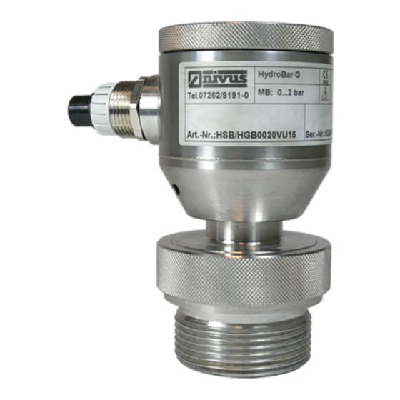
- Page 37 Installation and Connection Fig. 7-7 Sensor – HydroBar G II Pressure and Level Sensors - rev. 09 / 12.10.2017 page 37...
- Page 38 Instruction manual Pressure and Level Sensors Fig. 7-8 Sensor – AquaBar BS page 38 Pressure and Level Sensors - rev. 09 / 12.10.2017...
- Page 39 Installation and Connection Fig. 7-9 Sensor – AquaBar II Pressure and Level Sensors - rev. 09 / 12.10.2017 page 39...
-
Page 40: Connection
To achieve this use the cable shield (submersible sen- sors) or the ground clamp within the enclosure (pressure sensors). When using the probes in connection with NIVUS Ex- GPRS data loggers Types NivuLog Easy and NivuLog 2 Ex (N) connect the shield to the GND/Earth clamp. - Page 41 Installation and Connection Sensor body Protective cap (transportation lock, remove for operation) Cable Straining clamp Pressure compensation hose + filter element Fig. 7-10 Overview cable sensors Pressure and Level Sensors - rev. 09 / 12.10.2017 page 41...
-
Page 42: Pin Configuration
Instruction manual Pressure and Level Sensors 7.2.4 Pin configuration Connector pin out Electrical connections DIN 43650 Binder 723 Bulgin Label Cable (5-pin) Buccaneer colours Supply + (In+) + UB/US+ (white)* Supply - (In-) – blue UB/US- (brown)* Ground / PE Ground pin 5 GND / PE shield... -
Page 43: Power Supply
Installation and Connection 7.2.6 Power supply The supply voltage may vary between 12...36 V DC (14...28 V DC in Ex areas). Note however that the possible load resistance depends on the supply voltage. 18 Volt - max. 300 Ohm 24 Volt - max. 600 Ohm Power and signal circuit In type of protection “Intrinsic Safety Ex ia IIC/IIB“... -
Page 44: Initial Start-Up
Instruction manual Pressure and Level Sensors Initial Start-up Notes to the user Before you connect and operate a pressure or level sensor you should strictly follow the notes below! This instruction manual contains all necessary information to operate the sensors. It is addressed to qualified technical personnel who have appropriate knowledge about measurement technology and waste water hydraulics. -
Page 45: Maintenance And Cleaning
Interval The sensors are conceived to be virtually free of maintenance and wear. NIVUS recommends having them inspected by the NIVUS customer ser- vice once per year. Depending on the area of use the maintenance inter- vals however may vary. -
Page 46: Dismantling/Disposal
Instruction manual Pressure and Level Sensors To clean the diaphragm, remove the protective cap as follows: Sensor unit Protective cap Measurement cell Tool to open (screw driver or similar) Fig. 9-1 Removing the protective cap By hand: − Hold the probe unit (1), then −... -
Page 47: Index
Index 10 Index Applicable documentation ..6 Names ......... 3 Approval ........13 Operating permit ....... 10 Cleaning ........45 Overview ........11 Connection ....... 29 Connections ......10 Construction ......21 Parts subject to wear and tear ... 20 Copyright ........ -
Page 48: Certificates And Approvals
Le produit désigné ci-dessous: Bezeichnung: AquaBar II, AquaBar BS, HydroBar G II, NivuBar H II,NivuBar G II, Description: NivuBar Plus II, UniBar E Désignation: Typ / Type: HSB0…. erklären wir in alleiniger Verantwortung, dass die auf dem Unionsmarkt ab dem Zeitpunkt der Unterzeichnung bereitgestellten Geräte die folgenden einschlägigen Harmonisierungsvorschriften der Union erfüllen:... - Page 49 EU Konformitätserklärung NIVUS GmbH Im Täle 2 75031 Eppingen EU Declaration of Conformity Telefon: +49 07262 9191-0 Déclaration de conformité UE Telefax: +49 07262 9191-999 E-Mail: info@nivus.com Internet: www.nivus.de Für das folgend bezeichnete Erzeugnis: For the following product: Le produit désigné ci-dessous: Bezeichnung: "Ex"...
- Page 50 EU Konformitätserklärung NIVUS GmbH Im Täle 2 75031 Eppingen EU Declaration of Conformity Telefon: +49 07262 9191-0 Déclaration de conformité UE Telefax: +49 07262 9191-999 E-Mail: info@nivus.com Internet: www.nivus.de Für das folgend bezeichnete Erzeugnis: For the following product: Le produit désigné ci-dessous: Bezeichnung: "Ex"...
- Page 51 For the following product: Le produit désigné ci-dessous: Bezeichnung: "Ex" HydroBar G II Ex / NivuBar G II Ex / NivuBar Plus II Ex Description: "Ex" HydroBar G II Ex / NivuBar G II Ex / NivuBar Plus II Ex Désignation:...
Need help?
Do you have a question about the NivuBar Plus II and is the answer not in the manual?
Questions and answers