Table of Contents
Advertisement
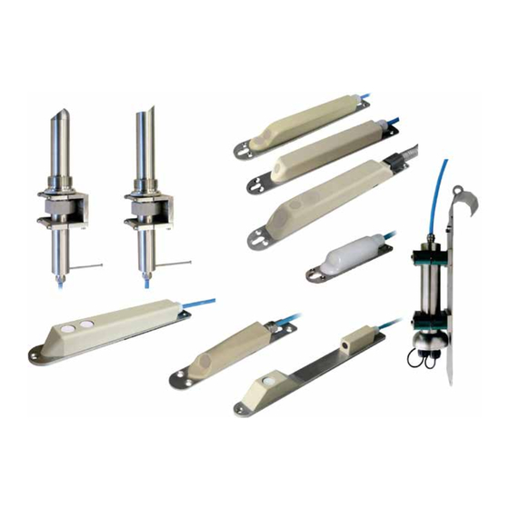
Technical Instructions for
Correlation Sensors
Correlation Sensors and external Electronic Box
as of Firmware Version:
NIVUS GmbH
Im Taele 2
75031 Eppingen, Germany
Phone: +49 (0) 72 62 / 91 91 - 0
Fax: +49 (0) 72 62 / 91 91 - 999
E-mail: info@nivus.com
Internet: www.nivus.com
Correlation Sensors – Rev. 07 as of 20.04.2016
Technical Instructions for
(Original technical instructions – German)
1.58 (POA-V2)
1.59 (OCL-L1)
1.58 (CS2)
1.64 (EBM)
®
Page 1
Advertisement
Table of Contents


Need help?
Do you have a question about the CSM Series and is the answer not in the manual?
Questions and answers