Table of Contents
Advertisement
Quick Links
Advertisement
Table of Contents

Related Manuals for United Technologies Interlogix DDI602U-F1


Summary of Contents for United Technologies Interlogix DDI602U-F1
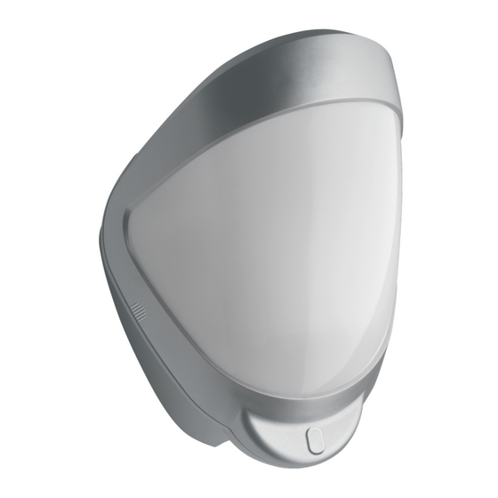
- Page 1 DDI602U-F1 Outdoor Dual PIR Detector Installation Sheet ( ) 1 STANDBY CURRENT DI601 = 7MA DDI602 = 11MA PROGRAM ALARM TAMPER ALARM 12V DC © 2019 UTC Fire & Security Americas Corporation, Inc. P/N 1069154U-F1 (EN) • REV D • ISS 01MAR19 1 / 7...
- Page 2 Long range / 82 . ft section MASK THIS SECTION Short / medium range 6 m 20 ft OFF FOR PET ALLEY to 18 / 59 . ft section APPLICATIONS UP - ° 2 0° 10 m 33 ft 10 m 33 ft 8 m 26 ft 8 m 26 ft 6 m 20 ft...
-
Page 3: En: Installation Sheet
( ) 1 STANDBY CURRENT DI601 = 7MA DDI602 = 11MA PROGRAM ALARM TAMPER ALARM 12V DC The electronics module is acrylic coated for additional component stability. It is encased in a vandal-resistant, high- impact, UV stabilized plastic housing with an opaque polyethylene front cover ensuring that the sensor is impervious to and unaffected by weather conditions. -
Page 4: Connecting The Unit
A hole-drilling template is provided. Terminal Label Description 3, 4 TAMPER N/C Tamper relay, normally closed Notes 5, 6 ALARM N/O Alarm relay, normally open • Leave a minimum 10 cm (4 inches) clearance above +, − 12V DC the top of the detector housing to allow the cover and 7, 8 12 V power supply... -
Page 5: Programmable Options
Figure 12 shows the pattern for the minimum range (10 m / Value 33 ft.) In this case masking the top section of the lens reduces Option the range to 6 meters. Pulse count Figure 13 shows possible alignments when the detector is Detection LED OFF* mounted close to a wall. -
Page 6: Specifications
Note: When you conduct a walk test, make sure that the front Cable < 500 m / 1640 ft. Utilising all three outputs (including tamper) cover is in place. Do not conduct walk tests with the cover — eight-core 16/0.2 mm² / 20 AWG removed. - Page 7 For customer support, see www.interlogix.com/customer- support. P/N 1069154U-F1 (EN) • REV D • ISS 01MAR19 7 / 7...
Need help?
Do you have a question about the Interlogix DDI602U-F1 and is the answer not in the manual?
Questions and answers