Table of Contents
Advertisement
Quick Links
Ardwolf A10 FINGERPRINT KEYPAD LOCK INSTALLATION
INSTRUCTIONS
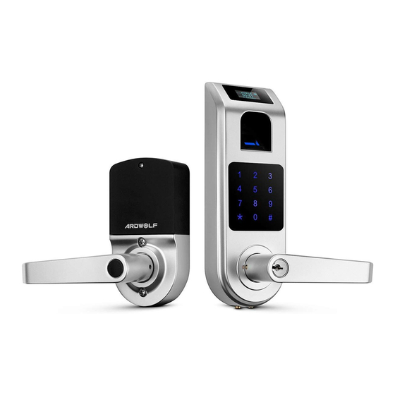
Ardwolf A10 Fingerprint Touchscreen Door Lock
Tools needed for new installation:
Installation Instructions
Pencil, Chisel, Tape Measure, Hammer, Phillips Screwdriver, 1" (25 mm) & ⅛" (3
mm) Drill Bits, 2 ⅛" (54 mm) Hole Boring Bit, Power Drill.
1. Mark door.
1.1 Mark centerline on door and jamb (see fig. 1).
finger on top of the sensor.
1.2 Stand so door swings towards you.
2. Drill holes on door (see fig. 2, and 3), dimension 8 mm hole is optional.
You hear three short beeps
3. Install Latch.
3.1 Latch is adjustable, you may set the latch to either
2 ⅜" (60 mm) or 2 ¾" (70 mm) backset (see fig.4).
3.2 Use faceplate as a pattern for mortise and pilot
holes. The faceplate should fit flush (see fig. 5).
3.3 Install as shown for appropriate latch type. Ensure
bevel faces doorjamb.
3.4 Check square hole edge on the latch spindle. The
square hole edges MUST are either parallel or vertically
aligned with latch centerline (see fig. 6), otherwise refer
fig. 7 to adjust latch spindle.
1
Advertisement
Table of Contents

Related Manuals for Ardwolf A10


Summary of Contents for Ardwolf A10
- Page 1 Ardwolf A10 FINGERPRINT KEYPAD LOCK INSTALLATION INSTRUCTIONS Ardwolf A10 Fingerprint Touchscreen Door Lock Tools needed for new installation: Installation Instructions Pencil, Chisel, Tape Measure, Hammer, Phillips Screwdriver, 1” (25 mm) & ⅛” (3 mm) Drill Bits, 2 ⅛” (54 mm) Hole Boring Bit, Power Drill.
- Page 2 4. Prepare doorjamb (see fig. 8). 4.1 Mark centerlines on jamb exactly opposite center of latch hole. 4.2 Make rectangle holes as shown. 4.3 Use strike as a pattern for mortise and pilot holes. Strike should fit flush. Part II. Fingerprint Keypad Lock Installation Instructions...
- Page 3 (A) Key (F) Latch (A) Mounting Screws (B) Outside Lever (G) Latch/Strike Screws (B) Inside Lever (C) Cylinder (H) Strike (M) Cover (D) Outside chassis (I) Inside chassis (N) Cover Screw (E) Lever Catch (J) Allen Screw (O) Allen Wrench The lock comes with two (K) Mounting Screws M5x60 2⅜”...
- Page 4 3.4 Insert Cylinder in Lever Spindle. The Cylinder’s tail toward left if you want to set lock as left-handed (see fig. 7b), otherwise the Cylinder’s tail toward right (see fig. 8b). 3.5 Put lever on Lever Spindle (see fig. 7c, 8c). The lever will stop at half way when you push Lever in.
- Page 5 fig. 12 fig. 13 nstallation Optio The lock will stay on vertical position on the door as long as the two mounting screws were tied up in most case. You may put a tapping screw on inside chassis to increase lock stability. 1.
Need help?
Do you have a question about the A10 and is the answer not in the manual?
Questions and answers