Advertisement
Quick Links
Advertisement

Related Manuals for impulce 2 Back Extension IT8011B

Summary of Contents for impulce 2 Back Extension IT8011B
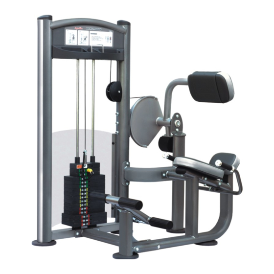
- Page 1 T8011B Back Extension Assembly Instructions...
-
Page 2: Table Of Contents
Table of contents Important Safety Instructions--------------------------------- 1 Exploded View Diagram------------------------------------------ 2 Hardware List-------------------------------------------------- ------ Parts List----------------------------------------------------- ---------- Assembly instructions------------------------------------------... -
Page 3: Important Safety Instructions
Important Safety Instructions Before beginning any fitness program, you should obtain a complete physical examination from your physician. When using exercise equip- ment, basic precautions should always be taken, including the following: * Read all instructions before using the Back Extension These instruc- tions are written to ensure your safety and to protect the unit. -
Page 4: Exploded View Diagram
T8011B Back Extension Exploded View Diagram... -
Page 5: Hardware List
Hardware List 1 10 14 0 Millimeters Inches... -
Page 6: Parts List
Parts List Item No. Description QTY Item No. Description Main Upright Adj.stopper Low Cross Plug Seat Frame Half-pulley Cover Pivot Arm Nylon Bushing Adj.Shaft Set Screw M10×16 Φ Φ Cross Spacer 16× 12.2×12.5 Adj.Foot Plate Big Bearing Washer Angle Support Seat Pad Support Spacer Guide Tube... -
Page 7: Assembly Instructions
Assembly instructions Assembly of the Back Extension takes professional installers about 2 hours. If this is the first time you have assembled this type of equipment, plan to spend more time. It is strongly recom mended to assemble the equipment by professional installers. You may find it quicker, safer, easier to assemble this equipment with the help of a friend, as some of components may be large, heavy or awkward to handle alone. - Page 8 Step1 Install the Adj.Foot Plates Align the Adj.Foot Plate(#7)to the Main Upright(#1),the Seat Frame(#3), the Rear Support(#59), then secure them by handle.
- Page 9 Step2 Assemble the Frame 1)Attach the Cross (#6)to the Main Upright (#1)using: Two Allen Bolts (#63)M10×115 Four Washers (#75) 11× 20×2 Φ Φ Two Nylon Locknuts (#78)M10 2)attach the Low Cross (#2)to the Main Upright (#1)using: Two Allen Bolts (#63)M10×115 Four Washers (#75) 11×...
- Page 10 Step3 Assemble the Pedal Support 1)Attach the Guide tube (#10)to the Seat Frame (#3)using: Two Allen Bolts (#65)M10×70 Four Washers (#75) 11× 20×2 Φ Φ Two Nylon Locknuts (#78)M10 2)Attach the Nylon Stem Button (#44)to the Slide Frame (#36)then insert them to the Guide Tube (#10),secure them using: One Shoulder Bolt (#68)M8×20 3)Make sure the Slide Frame can Slide smoothly.
- Page 11 Step4 Assemble the Pedal Attach the Pedal (#43) to the Slide Frame (#36) using: Eight Allen Bolts (#92) M8×20 Eight Spring Washers (#80) Φ Eight Washers (#76) Φ 9× 22×2 Φ...
- Page 12 Step5 Assemble the Pivot Arm 1)Attach the Pillow Block (#15)to the Main Upright (#1) using: Two Allen Bolts (#60)M12×40 Four Washers (#74) 13× 24×1.5 Φ Φ Two Nylon Locknuts (#77)M12 2)Insert the Adj.Shaft(#5) into the Main Upright(#1)and through the Pillow Block (#15). 3)Attach the Counter Poise Block (#27)to the Pivot Arm (#4) using: Two Shoulder Bolts (#69)M8×25...
- Page 13 Step6 Assemble the Cam Insert the Adj. Shaft (#5)through the Spacer (#13), the Cam (#8)and the Main Upright (#1), next, secure the Cam (#8)to the Adj.Shaft (#5)using the Key (#93).
- Page 14 Step7 Assemble the Pillow Block 1)Insert the Short Spacer (#14)onto the Adj.Shaft (#5). 2)Attach the Pillow Block (#15)to the Main Upright (#1) using: Two Allen Bolts (#60)M12×40 Four Washers (#74) 13× 24×1.5 Φ Φ Two Nylon Locknuts(#77)M12 3)Secure the Adj.Shaft (#5)to the Pillow Block (#15) using: One Allen Bolt (#71)M10×25 One Spring Washer (#79) 10...
- Page 15 Step8 Assemble the Angle Support 1)Attach the Angle Support (#57)to the Adj.Shaft (#5) using: One Allen Bolt (#71)M10×25 One Spring Washer (#79) 10 Φ One Washer (#75) 11× 20×2 Φ Φ One Outer Washer (#33) One Spacer (#58) 2)Attach the Angle Support (#57)to the Rear Support (#59)using: One Allen Bolt (#61)M12×120 One Spring Washer (#85)
- Page 16 Step9 Assemble the Weight Plates 1)Insert both the Guide Rods (#20)into the Main Upright (#1). 2)Slide the Weight Rubber Bumper (#28)down onto each Guide Rod(#20). 3)Carefully begin sliding the Weight Plate one by one in sequence :#29,#30,#31,#41 4)Align both the top ends of Guide Rods (#20)to the Main Upright (#1)and secure them using: Two Allen Bolts (#64)M10×75 Two Spring Washers (#79) 10...
- Page 17 Step10 Route Cable 1)Put the clip tied on the weight pin leash onto the Top Plate(#41) as shown,next connect the Cable(#40) to the Top Plate(#41). 2)Route the Cable(#40) up and over the two Pulleies A (#19).then secure them to the Main Upright(#1) using two Allen Bolts(#67) M10×45 four Washers(#75) Φ...
- Page 18 Ja m N ut Cl ip Top plate For Step10...
- Page 19 Step11 Assemble the Decal Plates 1)Attach the two Decal Plates(#18,86) to the Main Upr- ight(#1) using: fourteen Butttons(#38) 2)Attach the Weight Shroud (#21)to the Main Upright (#1) using: four Bolt Covers(#48) four Plastic Washers(#47) four Chamfer Bolts(#73) The Front Decal Plate(#18) with the exercise instr - ctions printed on it should be attached in the front Note of the Main Upright(#1).
- Page 20 Step12 Assemble the Seat Pad and the Plastic Cap 1)Attach the Seat Pad(#17) to the Seat Support(#9) using two Washers(#75) 11× 20×2 Φ Φ two Allen Bolts(#70) M10×30 2)Insert the Seat Support(#9) into the Seat Frame(#3) , lock it into place with the seat pop pin(#46) and the Allen Screw(#68).
Need help?
Do you have a question about the Back Extension IT8011B and is the answer not in the manual?
Questions and answers