Table of Contents
Advertisement
Quick Links
Overview .............................................................. 2
Tools Needed......................................................... 2
Hardware............................................................... 2
Assembly............................................................ 3-4
Document 101289 RevA
Document 101289 RevA
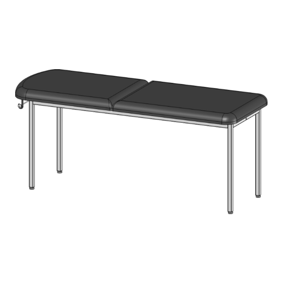
Model 2010
Installation.......................................................... 5
Maintenance ...................................................... 6
Accessories ...................................................... 6
Limited Warranty ............................................... 6
1
Printed in USA © 2010
Printed in USA © 2010
Advertisement
Chapters
Table of Contents

Subscribe to Our Youtube Channel
Related Manuals for brewer BrewerElement 2010


Summary of Contents for brewer BrewerElement 2010
-
Page 1: Table Of Contents
Model 2010 Installation............5 Overview .............. 2 Maintenance ............6 Tools Needed............2 Hardware............... 2 Accessories ............6 Assembly............3-4 Limited Warranty ..........6 Document 101289 RevA Document 101289 RevA Printed in USA © 2010 Printed in USA © 2010... -
Page 2: Overview
OVERVIEW COMPONENT IDENTIFICATION Perform the following sequence in order when setting up NOTE: Save all packaging in case re-shipment is re- the table: quired. Unpacking NOTE: Inspect all boxes and contents for damage. Assembly Report any damage to the carrier immediately. Leveling the Table Installing the Paper Roll MODEL 2010... - Page 3 MODEL 2010 STEP 1 Notch Screw C Screw C STEP A: Start with table frame inverted: note the position of the Notch in the drawing above is facing upwards. STEP B: Positon legs (see drawing above). Insert Screws C (1/4”-20 x 1 1/4”) by hand. Tighten screws using Allen Wrench provided.
- Page 4 MODEL 2010 STEP 2 STEP A: Install J-Bolts as shown in Figure A. J-Bolt R Thread Nut L (3/8”) completely onto J-Bolt. Nut L Place Washer M onto J-Bolt and thread Washer M into Backrest as shown in Figure A. Position J-Bolt toward head of table as shown and tighten nut against backrest.
-
Page 5: Installation
INSTALLATION Leveling the Table A Leveling Screw Pad is located at each corner under the table’s base. Adjust the four Leveling Screw Pads, by turning them up or down, to achieve a solid, level installation. Leveling Screw Pad Document 101289 RevA Printed in USA ©... -
Page 6: Maintenance
LIMITED WARRANTY and service for a period of three (3) years from date of shipment. The Brewer Company warrants its power tables to be free from defects in parts and workmanship under normal use and service for a period of three (3) years from date of shipment. The Brewer Company warrants its exam tables to be free from defects in parts and workmanship under normal use and service for a period of three (3) years from date of shipment. - Page 7 Models 2030 and 2040 Overview ............... 2 Operation ............. 9 Tools Needed ............2 Maintenance ............10 Hardware............... 2 Accessories ............10 Assembly............3-8 Limited Warranty ..........10 Installation............. 9 Document 101290 RevA Printed in USA © 2010 Document 101290 RevA Printed in USA ©...
-
Page 8: Overview
OVERVIEW COMPONENT IDENTIFICATION Perform the following sequence in order when setting up NOTE: Save all packaging in case re-shipment is re- the table: quired. Unpacking NOTE: Inspect all boxes and contents for damage. Assembly Report any damage to the carrier immediately. Leveling the Table Installing the Paper Roll MODELS 2030 &... - Page 9 MODELS 2030 and 2040 STEP 1 Notch Notch Screw C Screw C STEP A: Start with table frame inverted: note the position of the Notch in the drawing above is facing upwards. STEP B: Positon legs (see drawing above). Insert Screws C (1/4”-20 x 1 1/4”) by hand. Tighten screws using Allen Wrench provided.
- Page 10 MODELS 2030 and 2040 STEP 2 Caps Upper Leg Screws STEP A: Remove 2 Upper Leg Screws at Head End of the Table, one on each of the two legs. (See illustra- tion above.) STEP B: Insert Caps into two leg tops and seat with a rubber mallet. STEP C: Install and tighten Upper Leg Screws.
- Page 11 MODELS 2030 and 2040 STEP 3 Snap Rivet Screw G Backrest Catch Snap Rivet Screw B Nut H STEP A: Install Backrest Catch as shown in the drawing above. CAUTION The Backrest Catch needs to be positioned on top of the Tab shown in STEP 2. STEP B: STEP B: Install Screw B (1/4”-20 x 2”) through frame rail and into Backrest Catch and tighten Nut H (1/4”-20).
-
Page 12: Assembly
MODELS 2030 and 2040 STEP 4 Detail of Hinge Assembly Screw G Head End Nut H STEP A: Align holes in Hinge with holes in frame. Hinge must be oriented as shown with Hinge mounting flange facing the Head End of the table. STEP B: Install 4 Screws G (1/4”-20 x 1/2”) into the Hinge and through the frame. - Page 13 MODELS 2030 and 2040 STEP 5 J-Bolt R J-Bolt R Screw D Bumper Screw D Backrest Support Bumper Nut L Washer M Clevis Pin Screw F Screw F Foot End Clevis Pin Cotter Pin Clevis Hinge Clevis Tab STEP A: Lay upholstered backrest on Foot End of frame as shown. STEP B: Slide backrest down until it bumps up against Hinge.
- Page 14 MODELS 2030 and 2040 STEP 6 Dowel Rod Rounded Back Section Corner J-Bolt R Foot End Backrest Screw A Bracket Screw B STEP A: Rotate Back Section until Backrest Bracket is engaged or top is horizontal on frame. STEP B: Set upholstery bottom on frame, with Rounded Corners placed at the Foot End of the table. STEP C: Install Screw A (1/4”-20 x 4”) through frame and into upholstery.
-
Page 15: Installation
INSTALLATION Leveling the Table A Leveling Screw Pad is located at each corner under the table’s base. Adjust the four Leveling Screw Pads, by turning them up or down, to achieve a solid, level installation. Leveling Screw Pad OPERATION Back Section To Raise Back Section: Lift Back Section of upholstery to desired inclination and secure Backrest Bracket into one of the six Backrest Catch slots. -
Page 16: Maintenance
Warranty: The Brewer Company warrants its products to be free from defects in parts and workmanship under normal use and service for a period of three (3) years from date of shipment. The Brewer Company warrants its power tables to be free from defects in parts and workmanship under normal use and service for a period of three (3) years from date of shipment. - Page 17 Models 2110 Installation............7 Overview ............... 2 Tools Needed ............2 Maintenance ............8 Hardware............... 2 Accessories ............8 Assembly............3-6 Limited Warranty ..........8 Printed in USA © 2010 Printed in USA © 2010 Document 101291 RevA Document 101291 RevA...
-
Page 18: Overview
OVERVIEW COMPONENT IDENTIFICATION Perform the following sequence in order when setting up NOTE: Save all packaging in case re-shipment is re- quired. the table: Unpacking NOTE: Inspect all boxes and contents for damage. Assembly Report any damage to the carrier immediately. Leveling the Table Installing the Paper Roll MODEL 2110... - Page 19 MODEL 2110 STEP 1 Notch Screw C Screw C STEP A: Start with table frame inverted: note the position of the Notch in the drawing above is facing upwards. STEP B: Positon legs (see drawing above). Insert Screws C (1/4”-20 x 1 1/4”) and snug up by hand only at this time.
- Page 20 MODEL 2110 STEP 2 Table Frame Screw B Screw B Screw B Screw B Shelf Support STEP A: With table in the upright position install Shelf Support using 4 Screws B (1/4”-20 x 2”). Tighten screws . STEP B: Tighten eight screws attaching legs to Table Frame from STEP 1 using Allen Wrench provided. Printed in USA ©...
- Page 21 MODEL 2110 STEP 3 STEP A: Install J-Bolts as shown in Figure A. J-Bolt R Thread Nut L (3/8”) completely onto J-Bolt. Nut L Place Washer M onto J-Bolt and thread Washer M into Backrest as shown in Figure A. Position J-Bolt toward head of table as shown and tighten nut against backrest.
- Page 22 MODELS 2110 STEP 4 Snap Rivets Shelf Snap Rivets Snap Rivets Lower Shelf Support STEP A: Insert the Shelf through either end of the table. Positon the Shelf so that the locating blocks, on the bottom of the Shelf, are straddling the Lower Shelf Support. STEP B: Install Snap Rivets into unused holes in legs and frame (see illustration above).
-
Page 23: Installation
INSTALLATION Leveling the Table A Leveling Screw Pad is located at each corner under the table’s base. Adjust the four Leveling Screw Pads, by turning them up or down, to achieve a solid, level installation. Leveling Screw Pad CAUTION DO NOT USE SHELF AS A STEP! Printed in USA ©... -
Page 24: Maintenance
Warranty: The Brewer Company warrants its products to be free from defects in parts and workmanship under normal use and service for a period of three (3) years from date of shipment. The Brewer Company warrants its power tables to be free from defects in parts and workmanship under normal use and service for a period of three (3) years from date of shipment. - Page 25 Models 2130 and 2140 Overview ............... 2 Operation ..............11 Tools Needed ............2 Maintenance ............12 Hardware............... 2 Accessories ............12 Assembly............3-10 Limited Warranty ..........12 Installation............11 Document 101292 RevA Document 101292 RevA Printed in USA © 2010 Printed in USA © 2010...
-
Page 26: Overview
OVERVIEW COMPONENT IDENTIFICATION Perform the following sequence in order when setting up NOTE: Save all packaging in case re-shipment is re- the table: quired. Unpacking NOTE: Inspect all boxes and contents for damage. Assembly Report any damage to the carrier immediately. Leveling the Table Installing the Paper Roll MODELS 2130 &... - Page 27 MODELS 2130 and 2140 STEP 1 Notch Screw C Screw C STEP A: Start with table frame inverted: note the position of the Notch in the drawing above is facing upwards. STEP B: Positon legs (see drawing above). Insert Screws C (1/4”-20 x 1 1/4”) and snug up by hand only at this time.
- Page 28 MODEL 2130 and 2140 STEP 2 Screw B Screw B Screw B Screw B Shelf Support STEP A : With table in the upright position install Shelf Support using 4 Screws B (1/4”-20 x 2”). Do not tighten at this time. Document 101292 RevA Printed in USA ©...
- Page 29 MODELS 2130 and 2140 STEP 3 Caps Upper Leg Screws Shelf Support STEP A: Remove 2 Upper Leg Screws at Head End of the Table, one on each of the two legs. (See illustra- tion above.) STEP B: Insert Caps into two leg tops and seat with a rubber mallet. STEP C: Install Upper Leg Screws.
- Page 30 MODELS 2130 and 2140 STEP 4 Screw G Backrest Catch Screw B Nut H STEP A: Install Backrest Catch as shown in the drawing above. CAUTION The Backrest Catch needs to be positioned on top of the Tab shown in STEP 3. STEP B: Install Screw B (1/4”-20 x 2”) through frame rail and into Backrest Catch and tighten Nut H (1/4”-20).
-
Page 31: Assembly
MODELS 2130 and 2140 STEP 5 Detail of Hinge Assembly Screw G Head End Nut H STEP A: Align holes in Hinge with holes in frame. Hinge must be oriented as shown with Hinge mounting flange facing the Head End of the table. STEP B: Install 4 Screws G (1/4”-20 x 1/2”) into the Hinge and through the frame. - Page 32 MODELS 2130 and 2140 STEP 6 J-Bolt R Screw D Bumper J-Bolt R Screw D Backrest Support Bumper Nut L Cotter Pin Washer M Screw F Screw F Clevis Pin Clevis Pin Foot End Clevis Clevis Tab Hinge STEP A: Lay upholstered backrest on Foot End of frame as shown. STEP B: Slide backrest down until it bumps up against Hinge.
- Page 33 MODELS 2130 and 2140 STEP 7 Rounded Back Section Corner Foot End Backrest Screw A Bracket Screw B STEP A: Rotate Back Section until Backrest Bracket is engaged or top is horizontal on frame. STEP B: Set upholstery bottom on frame, with Rounded Corners placed at the Foot End of the table. STEP C: Install Screw A (1/4”-20 x 4”) through frame and into upholstery.
- Page 34 MODELS 2130 and 2140 STEP 8 Dowel Rod Snap Rivets Shelf Snap Rivets Lower Shelf Support STEP A: Insert the Shelf through either end of the Table. Positon the Shelf so that the locating blocks, on the bottom of the Shelf, are straddling the Lower Shelf Support. STEP B: Install Snap Rivets into unused holes in legs and frame (see illustration above).
-
Page 35: Installation
INSTALLATION Leveling the Table A Leveling Screw Pad is located at each corner under the table’s base. Adjust the four Leveling Screw Pads, by turning them up or down, to achieve a solid, level installation. Leveling Screw Pad OPERATION Back Section To Raise Back Section: Lift Back Section of upholstery to desired inclination and secure Backrest Bracket into one of the six Backrest Catch slots. -
Page 36: Maintenance
(a) the design, manufacture, sale, delivery, installation, repair, operation, or use of products of The Brewer Company or any part thereof, (b) any actual or alleged failure or defect in products of The Brewer Company or any part thereof, or (c) any actual or alleged breach or non-performance by The Brewer Company of this limited warranty. - Page 37 Model 2210 Overview ............... 2 Drawer Removal ..........11 Tools Needed ............2 Maintenance ............12 Hardware..............2 Accessories ............12 Assembly............3-10 Limited Warranty ..........12 Installation............11 Document 101293 RevA Document 101293 RevA Printed in USA © 2010 Printed in USA © 2010...
-
Page 38: Assembly
OVERVIEW COMPONENT IDENTIFICATION Perform the following sequence in order when setting up NOTE: Save all packaging in case re-shipment is re- the table: quired. Unpacking NOTE: Inspect all boxes and contents for damage. Assembly Report any damage to the carrier immediately. Leveling the Table Installing the Paper Roll MODEL 2210... - Page 39 MODEL 2210 STEP 1 Notch Screw C Screw C STEP A: Start with table frame inverted: note the position of the Notch in the drawing above is facing upwards. STEP B: Positon Legs in corners (see drawing above). Insert Screws C (1/4”-20 x 1 1/4”) and snug up by hand only at this time.
- Page 40 MODEL 2210 STEP 2 Screw B Drawer Supports with holes upward and toward Foot End Screw B Screw B Drawer Supports with holes upward and Screw B toward Foot End Screw B Shelf Support STEP A: With table in the upright position install Shelf Support using 4 Screws B (1/4”-20 x 2”). Do not tighten at this time.
- Page 41 MODEL 2210 STEP 3 Top Rail Paper Shelf Head End Drawer Support Remove this Screw Only STEP A: Remove one Drawer Support screw from the Head End of the table as shown. STEP B: Insert Paper Shelf between the Top Rail and the loose Drawer Support. Make sure the Paper Shelf is mounted below the Tab as shown.
- Page 42 MODEL 2210 STEP 4 Screw G Paper Shelf Nut H Snap Rivets STEP A: Install Screw G (1/4”-20 x 1/2”) through Tab and Paper Shelf as shown. Tighten Nut H (1/4”-20) onto Screw G. Install 3 Snap Rivets into holes on Paper Shelf and the top of the frame rail. Document 101293 RevA Printed in USA ©...
- Page 43 MODEL 2210 STEP 5 Detail of Drawer Slide Bumpers LH Side RH Side Drawer Support Nut K Screw E Shelf Support Drawer Slide STEP A: The drawers can be installed so they open from the right hand side (RH Side) or the left hand side (LH Side) of the table.
- Page 44 MODEL 2210 STEP 6 STEP A: Install J-Bolts as shown in Figure A. Install J-Bolts onto Thread Nut L (3/8”) completely onto J-Bolt. upholstery top Place Washer M onto J-Bolt and thread J-Bolt R into Backrest as shown in Figure A. Position J-Bolt toward head of table as shown and tighten nut against backrest.
- Page 45 MODEL 2210 STEP 7 Snap Rivet Shelf Side Plate Snap Rivet Lower Shelf Support Screw B Snap Rivet STEP A: Loosen Screws B at the foot of the table where indicated just enough to allow installation of the Side Plate. STEP B: Mount Side Plate so that the slots of the plate straddle the Screws B that were just loosened.
- Page 46 MODEL 2210 STEP 8 CAUTION CAUTION MAXIMUM LOAD DO NOT USE SHELF AS A STEP! 15 LBS. PER DRAWER Drawer Slide Positioning Incorrect Positioning Correct Positioning To install drawers, pull drawer slides forward and align the slots of the drawer-mounted slides to their mate on the frame.
-
Page 47: Installation
INSTALLATION Leveling the Table A Leveling Screw Pad is located at each corner under the table’s base. Adjust the four Leveling Screw Pads, by turning them up or down, to achieve a solid, level installation. Leveling Screw Pad DRAWER REMOVAL Retaining Clips Drawer (Bottom View) -
Page 48: Maintenance
(a) the design, manufacture, sale, delivery, installation, repair, operation or use of products of The Brewer Company or any part thereof, (b) any actual or alleged failure or defect in products of The Brewer company or any part thereof, or (c ) any actual or alleged breach or non-performance by The Brewer Company of this limited warranty. - Page 49 Models 2230 and 2240 Overview ............... 2 Drawer Removal ..........15 Tools Needed ............2 Operation ............15 Hardware..............3 Maintenance ............15 Assembly............4-13 Accessories ............16 Installation............14 Limited Warranty ..........16 Document 101294 RevA Printed in USA © 2010 Printed in USA ©...
-
Page 50: Assembly
OVERVIEW COMPONENT IDENTIFICATION Perform the following sequence in order when setting up NOTE: Save all packaging in case re-shipment is re- the table: quired. Unpacking NOTE: Inspect all boxes and contents for damage. Assembly Report any damage to the carrier immediately. Leveling the Table Installing the Paper Roll MODELS 2230 &... - Page 51 MODELS 2230 and 2240 HARDWARE 1/4”-20 x 4” Screw A (Qty. 1) Allen Wrench (Qty. 1) 1/4”-20 x 2” Screw B (Qty. 11) 1/4”-20 x 1 1/4” Screw C (Qty. 8) Snap Rivet (Qty. 32) Bumper (Qty. 2) 10-24 x 1 1/4” Screw D (Qty. 2) 8-32 Nut K (Qty.
- Page 52 MODELS 2230 and 2240 STEP 1 Notch Screw C Screw C STEP A: Start with table frame inverted: note the position of the Notch in the drawing above is facing upwards. STEP B: Positon legs (see drawing above). Insert Screws C (1/4”-20 x 1 1/4”) and snug up by hand only at this time.
- Page 53 MODEL 2230 and 2240 STEP 2 Drawer Supports with holes upward and toward Foot End Screw B Screw B Screw B Drawer Supports Screw B with holes upward and toward Foot End Screw B Shelf Support STEP A: With table in the upright position install Shelf Support using 4 Screws B (1/4”-20 x 2”). Do not tighten at this time.
- Page 54 MODELS 2230 and 2240 STEP 3 Caps Upper Leg Screws Head End STEP A: Remove 2 Upper Leg Screws at Head End of the table, one on each of the two legs. (See illustra- tion above.) STEP B: Insert Caps into two leg tops and seat with a rubber mallet. STEP C: Install Upper Leg Screws.
- Page 55 MODELS 2230 and 2240 STEP 4 Top Rail Paper Shelf Drawer Support Head End Remove this Screw Only STEP A: Remove one Drawer Support screw from the Head End of the table as shown. STEP B: Insert Paper Shelf between the Top Rail and the loose Drawer Support. Make sure the Paper Shelf is mounted below the Tab as shown.
- Page 56 MODELS 2230 and 2240 STEP 5 Screw G Backrest Catch Snap Rivet Screw B Paper Shelf Nut H Snap Rivets STEP A: Install Backrest Catch as shown in the drawing above. CAUTION The Backrest Catch needs to be positioned on top of the Tab shown in STEP 4. STEP B: Install Screw B (1/4”-20 x 2”) through frame rail and into Backrest Catch and tighten Nut H (1/4”-20).
- Page 57 MODELS 2230 and 2240 STEP 6 Detail of Hinge Assembly Screw G Head End Nut H STEP A: Align holes in Hinge with holes in frame. Hinge must be oriented as shown with Hinge mounting flange facing the Head End of the table. STEP B: Install 4 Screws G (1/4”-20 x 1/2”) into the Hinge and through the frame.
- Page 58 MODELS 2230 and 2240 STEP 7 Detail of Drawer Slide Bumpers LH Side RH Side Drawer Support Drawer Slide Screw E Nut K Shelf Support STEP A: The Drawers can be installed so they open from the right hand side (RH Side) or the left hand side (LH Side) of the table.
- Page 59 MODELS 2230 and 2240 STEP 8 J-Bolt R Screw D J-Bolt R Screw D Bumper Backrest Support Bumper Nut L Cotter Pin Washer M Screw F Clevis Pin Screw F Cotter Pin Clevis Pin Foot End Clevis Clevis Tab Hinge STEP A: Lay upholstered backrest on Foot End of frame as shown.
- Page 60 MODELS 2230 and 2240 STEP 9 Rounded Corner Back Section Foot End Screw A Backrest Bracket Screw B STEP A: Rotate Back Section until Backrest Bracket is engaged or top is horizontal on frame. STEP B: Set upholstery bottom on frame, with Rounded Corners placed at the Foot End of the table. STEP C: Install Screw A (1/4”-20 x 4”) through frame and into upholstery.
- Page 61 MODELS 2230 and 2240 STEP 10 Snap Rivet Shelf Side Plate Screw B Lower Shelf Support Snap Rivet Snap Rivet STEP A: Loosen Screws B at the foot of the table where indicated just enough to allow installation of the Side Plate.
-
Page 62: Installation
INSTALLATION Leveling the Table (Figure A) A Leveling Screw Pad is located at each corner under the table’s base. Adjust the four Leveling Screw Pads, by turning them up or down, to achieve a solid, level installation. Installing the Paper Roll (Figure B) Slide the Dowel Rod through the paper roll and hang the Dowel Rod on the J-Bolts. -
Page 63: Drawer Removal
DRAWER REMOVAL Retaining Clips Drawer (Bottom View) To remove Drawer from bottom slide support: Fully extend the Drawer, locate the Retaining Clips and push both clips in a clockwise direction as you pull the Drawer forward and out. OPERATION Back Section To Raise Back Section: Lift Back Section of upholstery to desired inclination and secure Backrest Bracket into one of the six Backrest Catch slots. -
Page 64: Maintenance
Warranty: The Brewer Company warrants its products to be free from defects in parts and workmanship under normal use and service for a period of three (3) years from date of shipment. The Brewer Company warrants its power tables to be free from defects in parts and workmanship under normal use and service for a period of three (3) years from date of shipment.
Need help?
Do you have a question about the BrewerElement 2010 and is the answer not in the manual?
Questions and answers