Download Print this page
Husqvarna Kohler SV470 Workshop Manual

Husqvarna Kohler SV470 Workshop Manual

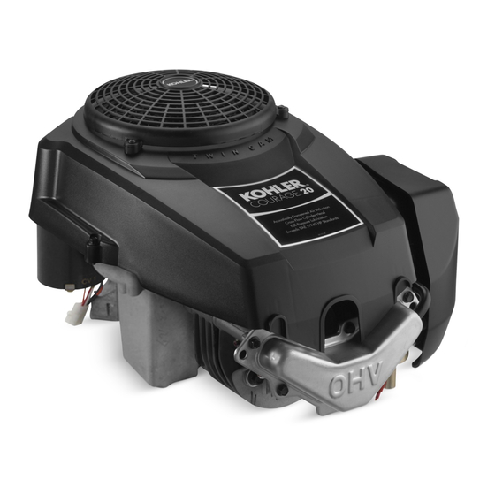
Kohler courage tractor engines

Advertisement

Workshop manual
Kohler Courage
Tractor Engines
English

Advertisement

loading

Summary of Contents for Husqvarna Kohler SV470

  • Page 1 Workshop manual Kohler Courage Tractor Engines English...
  • Page 2: Table Of Contents

    Contents Section 1. Safety and General Information ................Section 2. Special Tools ......................Section 3. Troubleshooting ..................... Section 4. Air Cleaner and Air Intake System ................ Section 5. Fuel System and Governor ..................Section 6. Lubrication System ....................Section 7. Electrical System and Components ..............Section 8.
  • Page 4: Section 1. Safety And General Information

    Section 1 SV470-600 Safety and General Information Section 1 Safety and General Information Safety Precautions WARNING severe CAUTION will minor NOTE For Your Safety! These precautions should be followed at all times. Failure to follow these precautions could result in injury to yourself and others.
  • Page 5 Section 1 Safety and General Information WARNING WARNING WARNING Explosive Gas can cause fires and Explosive Fuel can cause fires and Carbon Monoxide can cause severe acid burns. severe burns. severe nausea, fainting or death. Charge battery only in a well Stop engine before filling fuel tank.
  • Page 6 Section 1 Safety and General Information Engine Identification Numbers Model, Specification, and Serial Numbers Identification Decal Figure 1-1. Engine Identification Decal Location. A. Model No. SV 540 S Courage™ Vertical Shaft Engine Version Code Numerical Designation MODEL NO. SPEC. NO. SERIAL NO.
  • Page 7 Section 1 Safety and General Information Oil Recommendations Fuel Recommendations WARNING: Explosive Fuel! Gasoline is extremely flammable and its vapors can explode if ignited. Store gasoline only in approved containers, in well ventilated, unoccupied buildings, away from sparks or flames. Do not fill the fuel tank Oil Type while the engine is hot or running, since spilled fuel API (American...
  • Page 8 Section 1 Safety and General Information Periodic Maintenance WARNING: Accidental Starts! Disabling engine. Accidental starting can cause severe injury or death. Before working on the engine or equipment, disable the engine as follows: 1) Disconnect the spark plug lead(s). 2) Disconnect negative (-) battery cable from battery.
  • Page 9 Section 1 Safety and General Information Dimensions in millimeters. Inch equivalents shown in (). Figure 1-4. Typical Engine Dimensions.
  • Page 10 Section 1 Safety and General Information General Specifications¹ Air Cleaner Base Blower Housing and Sheet Metal Cam Lever Cam Gears...
  • Page 11 Section 1 Safety and General Information Cam Gears (cont'd.) Carburetor Closure Plate Connecting Rod Crankcase Crankshaft...
  • Page 12 Section 1 Safety and General Information Crankshaft (cont'd.) Cylinder Bore...
  • Page 13 Section 1 Safety and General Information Cylinder Bore I.D. (cont'd.) Cylinder Head Electric Starter Fan/Flywheel Governor Ignition ® Muffler Oil Filter 1.10...
  • Page 14 Section 1 Safety and General Information Oil Filter Pad Pipe Plug Oil Pump Oil Sentry Piston, Piston Rings, and Piston Pin Rectifier-Regulator Speed Control 1.11...
  • Page 15 Section 1 Safety and General Information Stator Throttle/Choke Controls Valve Cover Valves and Valve Lifters 1.12...
  • Page 16 Section 1 Safety and General Information General Torque Values Metric Fastener Torque Recommendations for Standard Applications Tightening Torque: N·m (in. lb.) + or - 10% Property Class Noncritical 10.9 12.9 Fasteners Into Aluminum Size Tightening Torque: N·m (ft. lb.) + or - 10% Property Class Noncritical Fasteners...
  • Page 17 Section 1 Safety and General Information 1.14...
  • Page 18 Section 2 Special Tools SV470-600 Section 2 Special Tools Special Tools You Can Make Flywheel Holding Tool Figure 2-1. Tool Catalog and Price List.
  • Page 19 Section 2 Special Tools 12 468 05-S Figure 2-2. Flywheel Holding Tool. Rocker Arm/Crankshaft Tool Figure 2-3. Rocker Arm/Crankshaft Tool.
  • Page 20: Section 3. Troubleshooting

    Section 3 Troubleshooting SV470-600 Section 3 Troubleshooting Troubleshooting Guide Engine Will Not Crank Engine Runs But Misses Engine Cranks But Will Not Start Engine Will Not Idle Engine Starts But Does Not Keep Running Engine Overheats Engine Starts Hard Engine Knocks...
  • Page 21 Section 3 Troubleshooting Engine Loses Power Engine Uses Excessive Amount of Oil External Engine Inspection Cleaning the Engine follow the manufacturer’s instructions and safety precautions carefully...
  • Page 22 Section 3 Troubleshooting Basic Engine Tests Crankcase Vacuum Test 10.2 cm (4 in.) before Incorrect Vacuum in Crankcase Possible Cause Solution...
  • Page 23 Section 3 Troubleshooting Compression Test Cylinder Leakdown Test 25 761 05-S Leakdown Test Instructions Leakdown Test Results...
  • Page 24: Section 4. Air Cleaner And Air Intake System

    Section 4 Air Cleaner and Air Intake System SV470-600 Section 4 Air Cleaner and Air Intake System Air Cleaner Air Cleaner Base Air Cleaner Element Air Cleaner Cover Optional Foam Precleaner Cleaner Cover Knobs Figure 4-1. Air Cleaner Assembly - Exploded View. Precleaner Service daily or before starting the every two...
  • Page 25 Section 4 Air Cleaner and Air Intake System 20 083 02-S Inspect Air Cleaner Components Outer Air Cleaner Cover Air Cleaner Base 20 083 01-S Paper Element Service every two months every 25 hours annually every 100 hours Do not Figure 4-2.
  • Page 26 Section 4 Air Cleaner and Air Intake System Reassembly above Figure 4-3. Breather Hose. Disassembly DO NOT OIL 5.5 N·m (48 in. lb.) 8.0 N·m (70 in. lb.) 5.5 N·m (48 in. lb.) do not...
  • Page 27 Section 4 Air Cleaner and Air Intake System Air Intake/Cooling System Clean Air Intake/Cooling Areas at all times Annually every 100 hours 7.5 N·m (65 in. lb.)
  • Page 28: Section 5. Fuel System And Governor

    Section 5 SV470-600 Fuel System and Governor Section 5 Fuel System and Governor Fuel Recommendations Gasoline/Alcohol blends WARNING: Explosive Fuel! Gasoline is extremely flammable and its vapors can explode if ignited. Store gasoline only in approved containers, in well-ventilated, unoccupied buildings, Gasoline/Ether blends away from sparks or flames.
  • Page 29 Section 5 Fuel System and Governor Fuel System Troubleshooting Guide Test Conclusion does does not does does not Fuel Filter annually hours Repair Fuel Pump Removal Operation Installation 5.9 N·m (52 in. lb.) Do not...
  • Page 30 Section 5 Fuel System and Governor Troubleshooting – Fuel System Figure 5-1. Pulse Fuel Pump. Carburetor Figure 5-2. Carburetor. WARNING: Explosive Fuel Gasoline is extremely flammable and its vapors can explode if ignited. Store gasoline only in approved containers, in well ventilated, unoccupied buildings, away from sparks or flames.
  • Page 31 Section 5 Fuel System and Governor Troubleshooting – Fuel System Possible Cause/Probable Remedy Condition Carburetor Adjustment Idle Speed (RPM) Adjustment Screw Idle Fuel Mixture Needle Figure 5-3. Fixed Main Jet Carburetor.
  • Page 32 Section 5 Fuel System and Governor Low Idle Mixture Adjustment* Low Idle Speed Setting Low Idle Speed Setting: “idle” “slow” in or out Low Idle Fuel Needle Setting: “idle” “slow” Lean Adjust to Midpoint Rich Figure 5-4. Optimum Low Idle Fuel Setting.
  • Page 33 Section 5 Fuel System and Governor Disassembly Throttle Lever and Shaft Dust Seal Throttle Plate Screw(s) Choke Lever and Shaft Choke Return Spring Throttle Plate Low Idle Speed Adjusting Choke Plate Screw and Spring Fuel Inlet Low Idle Fuel Adjusting Needle Needle and Spring with Float...
  • Page 34 Section 5 Fuel System and Governor Tool No. KO1018 Pry Out Plug Do Not Allow Tip to Strike Carburetor Body Pierce Plug with Tip Welch Plug Figure 5-6. Removing Welch Plug. Main Fuel Jet Removal Figure 5-8. Removing Choke Plate. Throttle Shaft Removal Fuel Inlet Seat Removal Do not...
  • Page 35 Section 5 Fuel System and Governor Welch Plug Installation • KO1017 Inspection Do not Tool No. KO1017 New Welch Plug Carburetor Body Figure 5-9. Installing Welch Plugs. Repair Reassembly Carburetor Reassembly Choke Shaft Installation counterclockwise...
  • Page 36 Section 5 Fuel System and Governor Figure 5-10. Installing Float and Fuel Inlet Needle. Figure 5-11. Fuel Shut-Off Solenoid. High Altitude Operation 5.1-6.2 N·m (45-55 in. lb.) Fuel Shut-off Solenoid half and full Unitized Throttle and Choke Control throttle Throttle Cable Adjustment Figure 5-12.
  • Page 37 Section 5 Fuel System and Governor Choke Adjustment Pencil or Drill Bit Screw Figure 5-15. Aligning Holes in Speed Control Bracket and Throttle Lever. Figure 5-13 Adjusting Unitized Throttle/Choke Control. Starting an Engine Equipped with Unitized Throttle and Choke Control For a Cold or Warm Engine “fast/choke on”...
  • Page 38 Section 5 Fuel System and Governor Do not Figure 5-17. Adjusting High Speed (RPM). To increase the high speed (RPM) For Operation To decrease the high speed (RPM) “fast/choke on” “slow” “fast” High Speed (RPM) Adjustment 3300 RPM 11.0 N·m (95 in. lb.) 7.5 N·m (65 in.
  • Page 39 Section 5 Fuel System and Governor Separate Throttle and Choke Control Install Separate Control Cables (See Figure 5-18). Throttle Control Installation Figure 5-18. Separate Choke and Throttle Cable Controls. Starting an Engine Equipped with Separate Control Cables “slow” “fast” “on” For a Cold Engine –...
  • Page 40 Section 5 Fuel System and Governor Changing the High Speed (RPM) on the Engines with Separate Controls (Increase or Decrease RPM) To increase the RPM: To decrease the RPM: Governed Idle Adjusting Screw Figure 5-19. Location of Governed Idle Adjusting Setting the Low Idle RPM Screw.
  • Page 41 Section 5 Fuel System and Governor Operation Do not counterclockwise 7.0-8.5 N·m (60-75 in. lb.) Figure 5-21. Governor Adjustment. Figure 5-22. Tightening Governor Lever Nut. Initial Adjustment 5.14...
  • Page 42 Section 5 Fuel System and Governor Governor Sensitivity Adjustment Throttle Lever Governor Lever High Speed Governed Governor Throttle White Green Idle RPM Lever Lever Spring Spring Hole No. Hole No. Figure 5-23. Governor Spring Location Chart. 5.15...
  • Page 43 Section 5 Fuel System and Governor 5.16...
  • Page 44: Section 6. Lubrication System

    Section 6 Lubrication System SV470-600 Section 6 Lubrication System Oil Recommendations Oil Type API (American Petroleum Institute) service class SG, SH, SJ or higher Figure 6-2. Oil Container Logo. Check Oil Level BEFORE EACH USE *Use of synthetic oil having 5W-20 or 5W-30 rating is acceptable, up to 4 C (40 F).
  • Page 45 Section 6 Lubrication System Change Oil and Oil Filter annually hours Always use a genuine Figure 6-3. Removing Dipstick. Kohler oil filter Oil Filter Oil Drain Plug Figure 6-4. Dipstick Seated. Figure 6-6. Oil Drain Plug, Oil Filter. Operating 14 N·m Range (125 in.
  • Page 46 Section 6 Lubrication System 2/3 to 1 turn Figure 6-7. Oil Pump on Intake Cam Shaft (Gerotors Removed from Pump Housing). Oil Filter Full-Pressure Lubrication System Operation ™ Oil Filter Figure 6-8. Oil Filter Location. Oil Sentry ™ Service ™ ™...
  • Page 47 Section 6 Lubrication System Testing the Oil Sentry Switch ™ ™ 2.0/5.0 psi ™ Installation continuity (switch closed) increase continuity (switch open) ™ 2.0/5.0 psi 90 psi maximum decrease continuity (switch closed) 2.0/5.0 psi; approaching 0 psi Pressure Switch Testing Oil Pressure Figure 6-9.
  • Page 48 Section 7 SV470-600 Electrical System and Components Section 7 Electrical System and Components ™ WARNING: Electrical Shock Never touch electrical wires or components while the engine is running. They can be sources of electrical shock. Spark Plug Type: ® 0.76 mm (0.030 in.) Thread Size: Reach: Wire Gauge...
  • Page 49 Section 7 Electrical System and Components Inspection Chalky White Deposits: Normal: Carbon Fouled: Worn: Wet Fouled:...
  • Page 50 Section 7 Electrical System and Components Electronic CD Ignition System Spark Plug Boot Spark Plug Terminal (C) Spark Plug Air Gap 0.203/0.305 mm (0.008-0.012 in.) Ignition Module Lamination (A) Kill Terminal (B) Magnet Flywheel Kill Switch or Off Position of Key Switch Figure 7-2.
  • Page 51 Section 7 Electrical System and Components Spark Plug Figure 7-3. Capacitive Discharge Ignition Module. Operation Preliminary Test Troubleshooting and Testing CD Ignition Systems...
  • Page 52 Section 7 Electrical System and Components CD Ignition System Troubleshooting Guide Conclusion Problem Test Engine Will Start low or 0 ohms high or infinity ohms 7,900 to 18,400 ohms Figure 7-4. Ignition Tester, SPX Part No. KO1046. Figure 7-5. Testing CD Ignition Module Secondary.
  • Page 53 Section 7 Electrical System and Components Battery Battery Test Do not Voltmeter Battery Charging WARNING: Explosive Gases! Battery Batteries produce explosive hydrogen gas while being charged. To prevent a fire or explosion, charge batteries only in well ventilated areas. Keep sparks, open flames, and other sources of ignition away from the battery at all times.
  • Page 54 Section 7 Electrical System and Components 3 Amp Charging Stator Lighting Lead (Yellow) Diode Lighting Stator Charging Lead (Black) Figure 7-7. 3 Amp/70 Watt Stator. Optional Oil Sentry Switch (Indicator Light) White Ground-To- Ignition Kill Lead Module Stator Spark Regulator- Plug Flywheel Rectifier...
  • Page 55 Section 7 Electrical System and Components Troubleshooting Guide 3 amp Battery Charging System with 70 Watt Lighting Stator Problem Test Conclusion more than 12.5 volts 12.5 volts or less 20 volts or more less than 20 volts high Charge Battery 0.5 ohms 0 ohms infinity ohms...
  • Page 56 Section 7 Electrical System and Components Troubleshooting Guide 3 amp/70 Watt Braking Stator Problem Test Conclusion more than 12.5 volts 12.5 volts or less 5 volts or more less than 5 volts Charge high Battery 0.15 ohms 0 ohms infinity ohms 13 volts or more less than 13 volts Lights...
  • Page 57 Section 7 Electrical System and Components Troubleshooting Guide 3 amp/70 Watt Braking Stator (cont.) Conclusion Problem Test 35 volts or more Lights less than 35 volts Battery Charging (Braking 0.2-0.4 ohms System Test) 0 ohms infinity ohms 7.10...
  • Page 58 Section 7 Electrical System and Components 9 or 15 amp Battery Charging System Ground-to-Kill Lead White Ignition Module Stator Key Switch Rectifier- Spark Flywheel Regulator Plug Violet Green Engine Green Optional Connector Optional Fuel Fuse Solenoid Optional Oil Sentry™ Indicator Light Optional Oil Sentry™...
  • Page 59 Section 7 Electrical System and Components Rectifier-Regulator 9 or 15 Amp Stator Figure 7-10. 9 or 15 amp Stator and Rectifier-Regulator. DC Volt Meter Rectifier-Regulator Flywheel Stator Ammeter Battery Figure 7-11. Proper Connection to Test 9 or 15 amp Charging System. 7.12...
  • Page 60 Section 7 Electrical System and Components Troubleshooting Guide 9 or 15 amp Regulated Battery Charging System Problem Test Conclusion 1. If voltage is 13.8-14.7 and charge rate 1. Trace B+ lead from rectifier-regulator to key increases when load is applied, the charging switch, or other accessible connection.
  • Page 61 Section 7 Electrical System and Components Electric Starters Operation Starting Motor Precautions Troubleshooting Guide - Starting Difficulties Problem Possible Fault Correction Battery Wiring Starter Does Not Energize Starter Switch or Solenoid Battery Brushes Starter Energizes But Turns Slowly Transmission Engine 7.14...
  • Page 62 Section 7 Electrical System and Components Starter Removal and Installation Starter Drive Service three years 150 hours Figure 7-13. Assembling Inner Half of Tool Around The Armature Shaft and Retaining Ring. Spring Retainer Retaining Ring Anti-Drift Spring Drive Pinion Drive Nut (Collar) Figure 7-12.
  • Page 63 Section 7 Electrical System and Components Retaining Ring Installation Retaining Ring Retainer Anti-Drift Spring Pinion Drive Nut (Collar) Hex. Flange Nuts Drive End Cap Thrust Washer Wave Washer Armature Frame Assembly Figure 7-15. Assembling Larger Inner Half Around Brush Carrier Assembly Spring Retainer.
  • Page 64 Section 7 Electrical System and Components Brush Replacement Figure 7-19. Armature Installed in Starter Frame. Figure 7-17. Removing Brush Carrier Assembly. Commutator Service Starter Reassembly Figure 7-20. Brush Carrier Assembly with Staples. Figure 7-18. Washers Installed on Armature. 7.17...
  • Page 65 Section 7 Electrical System and Components 2.2-4.5 N·m (20-40 in. lb.) 1.6-2.8 N·m (12-25 in. lb.), do not over torque 52 357 01-S Figure 7-21. Installing Brush Carrier Using Staples. 3.3-3.9 N·m (30-35 in. lb.) Figure 7-23. Assembled Starter. Figure 7-22. Torquing Thru Bolts. 7.18...
  • Page 66: Section 8. Disassembly

    Section 8 SV470-600 Disassembly Section 8 Disassembly WARNING: Accidental Starts! Disabling engine. Accidental starting can cause severe injury or death. Before working on the engine or equipment, disable the engine as follows: 1) Disconnect the spark plug lead. 2) Disconnect negative (-) battery cable from battery.
  • Page 67 Section 8 Disassembly Remove Oil Sentry Pressure Switch Remove Muffler ™ (on models so equipped) Figure 8-4. Removing Exhaust Flange Nuts. Figure 8-2. Removing Oil Sentry™ Switch. Remove Rectifier-Regulator Remove Blower Housing Figure 8-5. Removing Rectifier-Regulator. Figure 8-3 Removing Blower Housing Screws. Remove Electric Starter Disconnect Spark Plug Lead...
  • Page 68 Section 8 Disassembly Figure 8-6. Removing Electric Starter. Remove Air Cleaner Figure 8-9. Removing Air Cleaner Base Fasteners. Figure 8-7. Removing Air Cleaner Cover. Figure 8-10. Removing Air Cleaner Base and Breather Hose. Remove External Governor Components, Carburetor, and Fuel Pump WARNING: Explosive Fuel! Gasoline is extremely flammable and its vapors can explode if ignited.
  • Page 69 Section 8 Disassembly Figure 8-13. Removing Heat Deflector Screw and Ground Lead. Figure 8-11. Disconnecting Fuel Line from Carburetor. Figure 8-14. Disconnecting Fuel Solenoid Lead. Figure 8-12. Disconnecting Pulse Line from Fitting. Figure 8-15. Removing Carburetor.
  • Page 70 Section 8 Disassembly Figure 8-18. Removing Governor Lever. Figure 8-16. Removing Speed Control Bracket from Closure Plate. Figure 8-19. Removing Heat Deflector. Figure 8-17. Disconnecting Governor Spring.
  • Page 71 Section 8 Disassembly Remove Ignition Module Figure 8-22. Removing Grass Screen. Figure 8-20. Removing Lead from Clip (RFI Suppression Equipped Units. Figure 8-23. Removing Fan and Flywheel Mounting Hardware. Figure 8-21. Removing Ignition Module. Remove Grass Screen, Fan, and Flywheel...
  • Page 72 Section 8 Disassembly Figure 8-26. Removing Valve Cover Screws. Figure 8-24. Removing Flywheel Using Puller. Remove the Stator Figure 8-27. Valve Cover and Gasket Details. Figure 8-25. Removing Stator. Remove Valve Cover and Cylinder Head Figure 8-28. Loosening Adjustment Set Screw and Nut.
  • Page 73 Section 8 Disassembly Washer Figure 8-31. Removing Drain Back Check Ball from Crankcase. Disassemble Cylinder Head Figure 8-29. Removing Cylinder Head Bolts and Washer. Figure 8-32. Removing Spark Plug. Figure 8-30. Removing Cylinder Head and Gasket.
  • Page 74 Section 8 Disassembly Figure 8-33. Disassembling Rocker Arm Figure 8-35. Removing Closure Plate Screws. Components. Figure 8-34. Removing Valves with Spring Compressor. Remove Closure Plate Figure 8-36. Closure Plate and Gasket Removed from Crankcase.
  • Page 75 Section 8 Disassembly Disassemble Closure Plate Figure 8-39. Removing Cam Gears. Figure 8-37. Removing Governor Gear. Figure 8-40. Removing Cam Levers. Figure 8-38. Removing Oil Passage Cover and Gasket. Remove Cam Gears, Cam Shafts, and Oil Pump 8.10...
  • Page 76 Section 8 Disassembly Figure 8-43. Separating Oil Pump Assembly from Figure 8-41. Removing Exhaust Side Cam Shaft Intake Side Cam Shaft. and Slotted Thrust Washer. Remove Connecting Rod and Piston Outlet Seal Figure 8-44. Removing Connecting Rod Cap. Figure 8-42. Intake Cam shaft and Oil Pump Assembly.
  • Page 77 Section 8 Disassembly Figure 8-45. Removing Piston and Connecting Figure 8-47. Removing Piston Rings. Rod. Remove Crankshaft and Balance Weight Remove Piston from Connecting Rod Assembly Figure 8-48. Removing Crankshaft and Balance Figure 8-46. Separating Piston from Connecting Weight Assembly. Rod.
  • Page 78 Section 8 Disassembly Remove Governor Cross Shaft Figure 8-49. Removing Crank Gear Key. Figure 8-52. Removing Hitch Pin and Washer. Figure 8-50. Removing Balance Weight Screw. Figure 8-53. Removing Governor Cross Shaft. Figure 8-51. Disassembled Balance Weight. 8.13...
  • Page 79 Section 8 Disassembly Remove PTO and Flywheel Side Oil Seals Figure 8-54. Removing Seal with a Seal Puller. 8.14...
  • Page 80: Section 9. Inspection And Reconditioning

    Section 9 SV470-600 Inspection and Reconditioning Section 9 Inspection and Reconditioning Automatic Compression Release (ACR) Operation Control Pin Lower Section Cam Lobe Flyweight Cam Gear Spring Thrust Washer Figure 9-1. ACR Details.
  • Page 81 Section 9 Inspection and Reconditioning Crankcase Benefits Inspection and Service Honing Cam Gears Inspection and Service 250 RPM 60 strokes Crankshaft and Crank Gear Inspection and Service...
  • Page 82 Section 9 Inspection and Reconditioning 0.064 mm (0.0025 in.) Measuring Piston-to-Bore Clearance 0.013 mm (0.0005 in.) 8 mm (0.314 in.) Measure 8 mm (0.314 in.) Above the Bottom of Piston Skirt at Right Angles to Piston Pin. 8 mm (0.314 in.) Figure 9-2.
  • Page 83 Section 9 Inspection and Reconditioning Balance Weight-to-Eccentric Clearance Measuring Balance Weight Guide Pin and Guide Shoe-to-Closure Plate Guide Channel Running Clearance Measuring Balance Weight to Crankshaft Eccentric Ring(s) Clearance Figure 9-6. Measuring Balance Weight Guide Shoe. Figure 9-4. Measuring Balance Weight Bearing Surface.
  • Page 84 Section 9 Inspection and Reconditioning Flywheel Inspection Figure 9-8. Measuring Guide Pin O.D. Figure 9-9. Measuring Guide Shoe Hole I.D.
  • Page 85 Section 9 Inspection and Reconditioning Cylinder Head and Valves Inspection and Service Exhaust Valve Intake Valve Exhaust Insert Intake Insert Dimension Intake Exhaust Figure 9-10. Valve Details.
  • Page 86 Section 9 Inspection and Reconditioning Normal: Leakage: Bad Condition: Coking:...
  • Page 87 Section 9 Inspection and Reconditioning Excessive Combustion Temperatures: Stem Corrosion: Gum: Overheating:...
  • Page 88 Section 9 Inspection and Reconditioning Valve Guides Valve Seat Cutter Pilot intake 0.038/0.076 mm (0.0015/0.003 in.) Figure 9-11. Typical Valve Seat Cutter. exhaust 0.050/0.088 mm (0.0020/0.0035 in.) Lapping Valves intake 6.135 mm (0.2415 in.) 6.160 mm (0.2425 in.) Valve Seat Inserts Pistons and Rings Inspection...
  • Page 89 Section 9 Inspection and Reconditioning 0.08 mm (0.003 in.) Never reuse old rings. Stuck, Broken Rings Abrasive Scratched Rings Overheated or Deteriorated Oil Scored Piston and Rings Figure 9-12. Common Types of Piston and Ring Damage. 9.10...
  • Page 90 Section 9 Inspection and Reconditioning Never reuse old rings. Figure 9-14. Measuring Piston Ring Side Clearance. Install Piston Rings Piston Ring End Gap Identification Mark Figure 9-13. Measuring Piston Ring End Gap. Piston 0.04 mm (0.0016 Top Compression in.) Ring must Center Compression Ring...
  • Page 91 Section 9 Inspection and Reconditioning Oil Passages Figure 9-16. Oil Passages in Closure Plate. Connecting Rods Inspection and Service Oil Pump Assembly and Pressure Relief Valve Oil Passages Inspection and Service Figure 9-17. Oil Passages in Passage Cover. 4.0 N·m (35 in. lb.) Closure Plate and Passage Cover Inspection and Service Figure 9-18.
  • Page 92 Section 9 Inspection and Reconditioning Governor Gear and Shaft Procedure to Install Governor Shaft: Inspection 44.50 mm (1.750 in.) 0.101 mm (0.004 in.) Governor Gear Shaft 44.50 mm (1.750 in.)* Procedure to Remove Governor Shaft: *To Gasket Surface - Before Oil Passage Cover Plate and Gasket are Assembled Figure 9-19.
  • Page 93 Section 9 Inspection and Reconditioning 9.14...
  • Page 94: Section 10. Reassembly

    Section 10 Reassembly SV470-600 Section 10 Reassembly ™ Install PTO Side Oil Seal 5.5 mm (0.216 in.) Figure 10-1. Installing PTO Side Oil Seal. 10.1...
  • Page 95 Section 10 Reassembly Hitch Pin Thick Washer Oil Seal Figure 10-4. Securing Governor Shaft. Seal Depth Install Oil Pump Assembly and Intake Cam 5.5 mm (0.216 in.) Shaft Figure 10-2. PTO Seal Depth Details. Install Governor Cross Shaft 2.5 mm (0.098 in.) outer Intake...
  • Page 96 Section 10 Reassembly Pump Outlet Seal Figure 10-6. Assembled Intake Cam Shaft Details. Figure 10-8. Installing Oil Pump Outlet Seal. 3 mm upper "Open" Style "Closed" Style Figure 10-9. Oil Pump Outlet Seals. 4.0 N·m (35 in. lb.) Figure 10-7. Gerotor Gears Installed in Oil Pump. 10.3...
  • Page 97 Section 10 Reassembly 3/32" Allen Wrench PTO Side Guide Pin Figure 10-10. Checking Outlet Seal Passage Figure 10-12. Assembling Balance Weight to Opening (Open Style). Crankshaft. Intake Tube Crank Gear Key Oil Pump Oil Passage Seal Figure 10-11. Torquing Oil Pump Mounting Screws.
  • Page 98 Section 10 Reassembly Figure 10-16. Assembled Piston and Connecting Figure 10-14. Installing Crankshaft Assembly. Rod. Install Piston and Connecting Rod Figure 10-15. Installing Guide Shoe. Install Piston Rings Install Piston to Connecting Rod 10.5...
  • Page 99 Section 10 Reassembly Install Cam Levers 7.5 N·m (65 in. lb.) Intake Cam Figure 10-17. Direction Arrow on Piston. Follower Dimple Exhaust Follower Figure 10-20. Installing Cam Levers. Install the Exhaust Cam Shaft and Cam Gear Figure 10-18. Installing Piston and Connecting Rod.
  • Page 100 Section 10 Reassembly Figure 10-23. Spring Installed on ACR Weight. Exhaust Lever Figure 10-24. Hooking ACR Spring onto Exhaust Cam Gear. Exhaust Cam Shaft Figure 10-22. Exhaust Cam Shaft Installation. Figure 10-25. Installing Exhaust Cam Gear. 10.7...
  • Page 101 Section 10 Reassembly Install Intake Cam on Cam Shaft Install Flywheel Side Oil Seal 5 mm (0.196 in.) Figure 10-28. Installing Flywheel Side Oil Seal. Figure 10-26. Installing Intake Cam Gear and Install Closure Plate Gasket, Closure Thrust Washer. Plate, and Wiring Harness Install Crank Gear Do not Important!
  • Page 102 Section 10 Reassembly Guide Channel Guide Shoe Figure 10-29. Aligning and Installing Closure Plate. Figure 10-31. Closure Plate Fastener Torque Sequence. Assemble Cylinder Head 24.5 N·m (216 in. lb.) Figure 10-30. Closure Plate Installed. Figure 10-32. Assembling Cylinder Head. Install Cylinder Head Do not 10.9...
  • Page 103 Section 10 Reassembly IMPORTANT- 2. If the crankshaft has not been turned since the installation of the crank gear, turn it one (1) complete revolution. This will set the piston at top dead center (TDC) of the compression stroke, for proper valve lash adjustment later. Washer (Position 6) Figure 10-35.
  • Page 104 Section 10 Reassembly 0.076 mm (0.003 in.) 5.5 N·m (50 in. lb.) 0.076/0.127 mm (0.003/0.005 in.) Figure 10-37. Installing Guide Plates and Rocker Arm Pivot Studs. Figure 10-39. Adjusting Valve Clearance (Lash). Figure 10-40. Locking Adjustment Nut Set Screw. Install Valve Cover Figure 10-38.
  • Page 105 Section 10 Reassembly 11.0 N·m Install Wiring Harness (95 in. lb.) into new, as-cast holes, 7.5 N·m (65 in. lb.) Figure 10-41. Valve Cover Torque Fastener Sequence. Install Stator and Wiring Harness Figure 10-43. Installing B+ Lead into Connector. Install Stator Install Pipe Plug or Fitting and Pulse Line for Fuel Pump pipe sealant with Teflon...
  • Page 106 Section 10 Reassembly Install Fan and Flywheel WARNING: Damaging Crankshaft and Flywheel can Cause Personal Injury! Using improper procedures to install the flywheel can crack or damage the crankshaft and/or flywheel. This not only causes extensive engine damage, but can also cause personal injury, since broken fragments could be thrown from the engine.
  • Page 107 Section 10 Reassembly Install Electric Starter 3.6 N·m (32 in. lb.) Figure 10-49. Setting Air Gap. 6.0 N·m (55 in. lb.) 4.0 N·m (35 in. lb.) Figure 10-47. Installing Electric Starter. Install Ignition Module 0.203/0.305 mm (0.008/0.012 in.) 0.127 mm (0.005 in.) Do not Figure 10-48.
  • Page 108 Section 10 Reassembly Install New Spark Plug ® 0.76 mm (0.030 in.) 24-30 N·m (18-22 ft. lb.) Figure 10-53. Installing Intake Gasket and Heat Deflector. Figure 10-51. Installing Spark Plug. Models with one screw and one mounting stud only: Install Heat Deflector, Carburetor, Linkage and Air Cleaner Base ®...
  • Page 109 Section 10 Reassembly Throttle Linkage Choke Linkage Figure 10-57. Fuel Solenoid Lead Secured with Tie Strap. Figure 10-55. Installing Carburetor Assembly with Linkages. 8.0 N·m (70 in. lb.) Figure 10-58. Connecting Fuel Line to Carburetor. Figure 10-56. Securing Ground Lead. 10.16...
  • Page 110 Section 10 Reassembly 5.5 N·m (48 in. lb.) 8.0 N·m (70 in. lb.) 5.5 N·m (48 in. lb.) do not Tab on Top of Closure Plate Figure 10-59. Air Cleaner Base Upper Mounting Tab Details. Figure 10-62. Torquing Air Cleaner Fasteners. Install and Adjust Governor Lever Figure 10-60.
  • Page 111 Section 10 Reassembly 11.0 N·m (95 in. lb.) 7.5 N·m (65 in. lb.) 7.0-8.5 N·m (60-75 in. lb.) Rotate Counter Clockwise Figure 10-66. Attaching Speed Control Bracket. Install Fuel Pump (if equipped) Figure 10-64. Adjusting Governor and Linkage. Mounting Speed Control Bracket 6.5 N·m (55 in.
  • Page 112 Section 10 Reassembly Figure 10-70. Installing Blower Housing. Figure 10-68. Installing Fuel Pump. Install Rectifier-Regulator 11.0 N·m (95 in. lb.) 7.5 N·m (65 in. lb.) 6.0 N·m (55 in. lb.) 4.0 N·m (35 in. lb.) Notch Figure 10-71. Installing Blower Housing Screws. Figure 10-69.
  • Page 113 Section 10 Reassembly Oil Sentry™ Switch Figure 10-72. Installing Grass Screen. Figure 10-74. Installed Oil Sentry Switch. Install Air Cleaner Element, Precleaner, Install Oil Sentry™ or Pipe Plug and Air Cleaner Cover pipe sealant with Teflon ® ® 4.5-5.0 N·m (40-45 in. lb.) 4.5-5.0 N·m (40-45 in.
  • Page 114 Section 10 Reassembly Figure 10-76. Installing Precleaner. Figure 10-78. Torquing Exhaust Flange Nuts. Install Drain Plug, Oil Filter, and Oil 14 N·m (125 in. lb.) 2/3-1 turn Figure 10-77. Installing Air Cleaner Cover. Install Muffler 24.4 N·m (216 in. lb.) 7.5 N·m (65 in.
  • Page 115 Section 10 Reassembly Prepare the Engine for Operation Testing the Engine Before 5 psi 3300 RPM 10.22...
  • Page 116 114 03 04-26 2004W27...