
Related Manuals for Bailey IMCIS12


Summary of Contents for Bailey IMCIS12
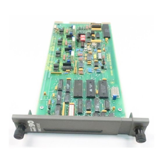
- Page 1 IMCIS12/IMQRS12 ® ® Control I/O Module and Quick Response I/O Module Process Control and Automation Solutions from Elsag Bailey Group...
- Page 2 The information contained in this document is subject to change without notice. Elsag Bailey, its affiliates, employees, and agents, and the authors and contributors to this publication specifi- cally disclaim all liabilities and warranties, express and implied (including warranties of merchantability and fit-...
- Page 3 Preface The IMCIS12 Control I/O and IMQRS12 Quick Response I/O ® modules bring process field signals into the INFI 90 OPEN Strategic Process Management System, and output INFI 90 OPEN signals to the process. The IMCIS12 and IMQRS12 modules are the functional equiva-...
- Page 4 ® List of Effective Pages Total number of pages in this instruction is 55, consisting of the following: Page No. Change Date Preface Original List of Effective Pages Original iii through vii Original 1-1 through 1-10 Original 2-1 through 2-7 Original 3-1 through 3-8 Original...
-
Page 5: Table Of Contents
Table of Contents Page SECTION 1 - INTRODUCTION ....................1-1 OVERVIEW ........................1-1 INTENDED USER ......................1-1 MODULE DESCRIPTION ....................1-1 INSTRUCTION CONTENT .....................1-3 HOW TO USE THIS MANUAL ..................1-3 DOCUMENT CONVENTIONS ..................1-4 GLOSSARY OF TERMS AND ABBREVIATIONS .............1-4 REFERENCE DOCUMENTS..................1-5 NOMENCLATURE ......................1-5 RELATED HARDWARE....................1-5 SPECIFICATIONS ......................1-6 SECTION 2 - DESCRIPTION AND OPERATION................2-1 INTRODUCTION......................2-1... - Page 6 ® Table of Contents (continued) Page SECTION 4 - OPERATING PROCEDURES................4-1 INTRODUCTION ......................4-1 MODULE STATUS INDICATOR ..................4-1 START-UP PROCEDURES .................... 4-2 FUNCTION CODE CONFIGURATION ................4-2 SECTION 5 - TROUBLESHOOTING...................5-1 INTRODUCTION ......................5-1 ERROR INDICATIONS AND CORRECTIVE ACTION ............5-1 Status LED......................
- Page 7 List of Figures Title Page 1-1. INFI 90 OPEN Communication Levels ..............1-2 2-1. Block Diagram .......................2-1 2-2. Analog Input Circuit Example ................2-2 2-3. Analog Output Circuit Example ................2-3 2-4. Digital Input Circuit Example.................2-5 2-5. Digital Output Circuit Example ................2-5 3-1. Switch and Jumper Locations ................3-3 3-2.
- Page 8 ® Safety Summary GENERAL Equipment Environment WARNINGS All components, whether in transportation, operation or storage, must be in a noncorrosive environment. Electrical Shock Hazard During Maintenance Disconnect power or take precautions to insure that contact with energized parts is avoided when servicing. SPECIFIC Disconnect power before installing dipshunts on the MMU back- WARNINGS...
- Page 9 Trademarks and Registrations Registrations and trademarks used in this document include: ® INFI 90 Registered trademark of Elsag Bailey Process Automation ® INFI-NET Registered trademark of Elsag Bailey Process Automation WBPEEUI240755B0...
-
Page 10: Section 1 - Introduction
SECTION 1 - INTRODUCTION OVERVIEW The IMCIS12 Control I/O and IMQRS12 Quick Response I/O modules bring four analog and three digital process field sig- nals into the INFI 90 OPEN system for processing and monitor- ing. They output four digital and two analog signals for process control. -
Page 11: Infi 90 Open Communication Levels
INTRODUCTION ® The I/O module has three connection points for external sig- nals and power (P1, P2 and P3). P1 connects to a common (ground) and +5 VDC and ±15 VDC power (refer to Table 5-2). P2 connects the module to the control module through the I/O expander bus (refer to Table 5-3). -
Page 12: Instruction Content
INSTRUCTION CONTENT This instruction is divided into eight sections and three appen- dices. Read this instruction before installing or operating the IMCIS12 or IMQRS12 module. A summary of section content follows: Introduction Contains a brief description, general usage information and technical specifications. -
Page 13: Document Conventions
IMCIS GLOSSARY OF TERMS AND ABBREVIATIONS Table contains those terms and abbreviations that are unique to Elsag Bailey or have a definition that is different from standard industry usage. Table 1-1. Glossary of Terms and Abbreviations Term Definition Engineering work station. -
Page 14: Reference Documents
INTRODUCTION REFERENCE DOCUMENTS Table lists Elsag Bailey instructions for equipment that is referenced in this instruction. Table 1-2. Reference Documents Number Document I-E92-501-2 Configuration and Tuning Terminal (CTT) I-E96-192-1 Operation, Operator Interface Station (40 Series) IIOIS42 I-E96-200 Function Code Application Manual... -
Page 15: Specifications
Termination unit, control I/O NKTM01 Cable, termination module NKTU01/11 Cable, termination unit NKTU02/12 Cable, termination module SPECIFICATIONS Table contains specifications relative to the IMCIS12 and IMQRS12 modules. Table 1-5. Specifications Property Characteristic/Value Power Requirements ± Voltage 5 VDC ( +15 VDC (-2.5%, +5%) -15 VDC (-5%, +2.5%) - Page 16 Single ended or differential voltage (1-5 VDC) Input impedance >1 MΩ ± Common mode voltage 10 VDC IMCIS12 Normal mode rejection >76 db at 50/60 Hz Common mode rejection 90 db from DC to 60 Hz Response time per channel 2.4 sec to 95% of final value...
- Page 17 INTRODUCTION ® Table 1-5. Specifications (continued) Property Characteristic/Value Analog I/O (continued) Analog outputs 2, 4-20 mA or 1-5 VDC 600 Ω/600 mH (maximum) Output load - current load Output load - voltage load >1 kΩ D/A resolution 10 bits for analog outputs Analog accuracy Input at 25°C (77°F) standard condition...
- Page 18 INTRODUCTION Table 1-5. Specifications (continued) Property Characteristic/Value Isolation Normal (per IEC 1010-1, IEC 255, IEC 60) Test Common Mode Mode Digital Input Channel to channel and channel to Insulation resistance 100 MΩ logic (100/500 VDC) Dielectric VAC (45 to 65 Hz) or VDC 1.4 kV rms/1 min.
- Page 19 INTRODUCTION ® Table 1-5. Specifications (continued) Property Characteristic/Value Magnetic and electromagnetic fields (continued) Damped oscillatory magnetic Peak value: 30 A/m field, 0.1 MHz and 1 MHz (IEC 1000-4-10, EN 61000-4-10) Radiated radio-frequency elec- Unmodulated rms: 10 V/m tromagnetic field, 80 MHz to Amplitude modulated: 80% AM (1 kHz) 1 GHz (ENV 50140) Radiated radio-frequency field,...
-
Page 20: Section 2 - Description And Operation
INTRODUCTION This section explains the inputs, outputs, logic power and con- nections for the IMCIS12 and IMQRS12 modules. The CIS and QRS modules are process field I/O interfaces for a multi-func- tion processor (MFP) module. The I/O module circuitry per- forms the following functions: Analog to digital (A/D) conversion. -
Page 21: Analog I/O
DESCRIPTION AND OPERATION ® ANALOG I/O The CIS and QRS modules can input four separate analog sig- nals configurable as voltage (one to five VDC) single ended or differential, or current (four to 20 milliamperes) field powered. It allows for a common mode (inputs change together propor- tionally) differential voltage of ±10 VDC. -
Page 22: Analog Input Circuit Calibration
DESCRIPTION AND OPERATION Analog Input Circuit Calibration The reference block generates accurate 1 VDC and 5 VDC sig- nals. The I/O module does not have potentiometers to adjust zero offset and gain for the A/D converter circuits. Instead, the MFP reads the reference voltages once per minute to calibrate the zero percent (1 VDC) and 100 percent (5 VDC) points;... -
Page 23: Digital I/O
DESCRIPTION AND OPERATION ® The analog output mode jumpers set the type of output, either current or voltage. If current mode is selected, the E/I circuits on the I/O module convert the voltage from the D/A converter to a current output. Refer to Analog Output Mode Jumpers (J9, J11, J13, J15) in Section 3 for details. -
Page 24: I/O Circuit Connections
DESCRIPTION AND OPERATION FIELD INPUT REF DI TO INPUT – CIRCUITRY DI REFERENCE REF DI T00324A Figure 2-4. Digital Input Circuit Example POWER FIELD OUTPUT FROM OUTPUT CIRCUITRY TP00085A Figure 2-5. Digital Output Circuit Example I/O CIRCUIT CONNECTIONS The I/O signals connect to the 30-pin card edge connector P3 of the CIS and QRS modules using a termination cable from a ter- mination unit (TU) or termination module (TM). -
Page 25: Universal I/O Expander Bus Interface
DESCRIPTION AND OPERATION ® connects the bus between the control and I/O modules. Cable assemblies can extend the bus to six MMUs. A control module and its I/O modules form an individual sub- system within a process control unit (PCU). The I/O expander bus between control module and I/O module subsystems must be separated. -
Page 26: Status Data
DESCRIPTION AND OPERATION The MFP reads a one byte value that consists of digital output readback values and digital input values. The digital input val- ues indicate the digital input states. Each bit corresponds to one input; the bit value reflects the state of that input, either open (logic 0) or closed (logic 1). -
Page 27: Section 3 - Installation
SPECIAL HANDLING NOTE: Always use the Elsag Bailey field static kit (part number 1948385 1), consisting of two wrist straps, ground cord assembly, alligator clip, and static dissipating work surface when working with static sensitive devices. -
Page 28: Unpacking And Inspection
UNPACKING AND INSPECTION 1. Examine the hardware immediately to verify it has not been damaged in transit. 2. Notify the nearest Elsag Bailey Sales Office of any such damage. 3. File a claim for any damage with the transportation com- pany that handled the shipment. -
Page 29: Switch And Jumper Locations
INSTALLATION MODULE STATUS LEDS DIGITAL INPUT JUMPERS EDGE CONNECTORS OPEN ADDRESS ANALOG OUTPUT ANALOG OUTPUT ANALOG INPUT SWITCH DEFAULT JUMPERS MODE JUMPERS MODE JUMPERS T00086A Figure 3-1. Switch and Jumper Locations OPEN MUST REMAIN ADDRESS CLOSED NOTE: OPEN POSITION = LOGIC 1 TP65205B Figure 3-2. -
Page 30: Analog Output Default Jumpers (J7, J8, J12, J14, J10, J16)
INSTALLATION ® Table 3-1. S1 Address Switch Settings (continued) ADDR ADDR 1 = OPEN; 0 = CLOSED Analog Output Default Jumpers (J7, J8, J12, J14, J10, J16) The analog output default jumpers determine the I/O module analog output default values. These are the values or levels for the analog outputs during system start-up (power up) or bus fault error (time-out). -
Page 31: Analog Output Mode Jumpers (J9, J11, J13, J15)
INSTALLATION Table 3-2. Analog Output Default Jumpers Time-Out Option Power-Up State Analog Go To Output Jumper Hold Jumper 100% Power-Up Analog Output Mode Jumpers (J9, J11, J13, J15) The analog output mode jumpers select the mode of each ana- log output. The mode can be set to current (four to 20 milliam- peres) or voltage (one to five VDC). -
Page 32: Digital Input Jumper Settings (J1, J2, J3, J4, J5, J6)
INSTALLATION ® Table 3-4. Analog Input Mode Jumpers Analog Voltage Mode Voltage Mode Jumpers Current Mode Input (Single Ended) (Differential) 1, 2, 3, 4 J17, J18, J19, J20 — NOTE: 1. Field/system powered analog inputs depend on TU/TM configuration. 2. Do not install jumpers for this configuration. Digital Input Jumper Settings (J1, J2, J3, J4, J5, J6) Jumpers J-1 through J-6 set the input voltage and the input mode (AC or DC). -
Page 33: Wiring Connections And Cabling
INSTALLATION The IMCIS12 and IMQRS12 modules insert into a standard INFI 90 OPEN module mounting unit (MMU) and each occupies one slot. Use the following installation procedures. 1. Verify the slot assignment of the module. Disconnect power before installing dipshunts on the MMU WARNING backplane. -
Page 34: Fusing
PREOPERATING ADJUSTMENTS The CIS and QRS modules do not require any adjustments prior to operation. 4 ANALOG INPUTS (1-5 VDC, 4-20 mA) 3 DIGITAL INPUTS NKTM01 IMCIS12/ (24/48/125 VDC, 120 VAC) NICS01 IMQRS12 NKTU02 2 ANALOG OUTPUTS (1-5 VDC, 4-20 mA) -
Page 35: Section 4 - Operating Procedures
SECTION 4 - OPERATING PROCEDURES INTRODUCTION This section explains the front panel indicator and start-up procedures for the IMCIS12 and IMQRS12 modules. MODULE STATUS INDICATOR The CIS and QRS modules have two (red/green) LEDs visible through the module front panel. When lit, the green LED indi- cates a good I/O module status. -
Page 36: Start-Up Procedures
OPERATING PROCEDURES ® START-UP PROCEDURES The multi-function processor (MFP) controls the start-up of the CIS and QRS modules; it is fully automatic. Function Code (FC) 79 in the MFP configuration enables the I/O module. Specification S1 (FC 79) is the I/O module address. It must be the same as the address set on the I/O module address switch (S1). -
Page 37: Section 5 - Troubleshooting
SECTION 5 - TROUBLESHOOTING INTRODUCTION This section explains the error indications and corrective actions for the IMCIS12 and IMQRS12 modules. ERROR INDICATIONS AND CORRECTIVE ACTION Status of the CIS and QRS modules can be obtained through an INFI 90 OPEN operator interface (e.g., Operator Interface Station, Engineering Work Station, Configuration and Tuning Terminal) or the front panel module status LED indicators. -
Page 38: Control Module Errors
TROUBLESHOOTING ® Table 5-1. Status LED Indications and Correction Actions (continued) LED State Indication Probable Cause Corrective Action Bus fault timer error Dipshunt not installed Verify dipshunt is installed in the I/O (FAIL) (time-out) between MFP and I/O expander bus socket on the MMU back- (continued) module plane between MFP and I/O module... -
Page 39: Module Pin Connections
TROUBLESHOOTING 2. Modify the address in the MFP configuration (FC 79 specifi- cation S1) to correspond with the address set on switch S1. Use an INFI 90 OPEN operator interface to modify the configu- ration (for procedures on how to modify a function code specifi- cation, refer to the appropriate instruction manual for the operator interface you are using). -
Page 40: P3 I/O Pin Connections
TROUBLESHOOTING ® Table 5-4. P3 I/O Pin Connections Signal Pin (+) Pin (-) Digital Output 1 Digital Output 2 Digital Output 3 Digital Output 4 Digital Input 1 Digital Input 2 Digital Input 3 +24 VDC Analog Output 1 Analog Output 2 Analog Input 1 Analog Input 2 Analog Input 3... -
Page 41: Section 6 - Maintenance
PREVENTIVE MAINTENANCE SCHEDULE Table is the preventive maintenance schedule for the IMCIS12 and IMQRS12 modules. The table lists the preventive maintenance tasks in groups according to their specified main- tenance interval. Instructions for tasks that require further explanation are covered under PREVENTIVE MAINTENANCE PROCEDURES. -
Page 42: Preventive Maintenance Procedures
MAINTENANCE ® Table 6-1. Preventive Maintenance Schedule Task Frequency Check cabinet, module mounting unit backplane assem- Every six bly, I/O module and termination device for dust. Clean as months or dur- necessary using an antistatic vacuum. If circuit board ing plant shut- cleaning is necessary, refer to procedure. -
Page 43: Edge Connector Cleaning
MAINTENANCE To wash the printed circuit board: 1. Clean the printed circuit board by spraying or wiping it with isopropyl alcohol (99.5% electronic grade). Use a foam tipped swab to wipe the circuit board. 2. Remove excess solvent by using compressed air to blow it free of the circuit board. - Page 44 MAINTENANCE ® There are exposed AC and DC connections inside the cabinet. These exposed electrical connections present a shock hazard that can cause injury or death. WARNING If input or output circuits are a shock hazard after disconnect- ing system power at the power entry panel, then the door of the cabinet containing these externally powered circuits must be marked with a warning stating that multiple power sources exist.
-
Page 45: Section 7 - Repair/Replacement Procedures
SECTION 7 - REPAIR/REPLACEMENT PROCEDURES INTRODUCTION This section explains the replacement procedures for an IMCIS12 and IMQRS12 modules. There are no special tools required to replace CIS and QRS modules. MODULE REPAIR/REPLACEMENT PROCEDURES If you determine the CIS or QRS module is faulty, replace it with a new one. -
Page 46: Section 8 - Support Services
SECTION 8 - SUPPORT SERVICES INTRODUCTION Elsag Bailey Process Automation is ready to help in the use and repair of its products. Contact the nearest sales office to make requests for sales, applications, installation, repair, overhaul and maintenance contract services. -
Page 47: Appendix A - Termination Unit (Ntcs04) Configuration
APPENDIX A - TERMINATION UNIT (NTCS04) CONFIGURATION INTRODUCTION The IMCIS12 and IMQRS12 modules can use an NTCS04 for termination. The termination unit can handle four analog inputs, two analog outputs, three digital inputs and four digital outputs. Dipshunts on the termination unit configure the I/O. - Page 48 TERMINATION UNIT (NTCS04) CONFIGURATION ® Table A-1. Analog Input Dipshunt Configuration Application/Signal Type Dipshunt Configuration XU1-XU4 System powered (4-20 mA) Externally powered (4-20 mA) Single ended voltage (1-5 VDC) Differential voltage (1-5 VDC) Table A-2. Analog Input Destination for Station Feedback Dipshunt Configuration Application/Signal Type (Station Designator/Analog Input)
- Page 49 TERMINATION UNIT (NTCS04) CONFIGURATION Table A-3. Analog Output Dipshunt Configuration Application/Signal Type Dipshunt Configuration XU9 Both outputs in voltage mode Output 1 in voltage mode, output 2 in current mode Output 1 in current mode, output 2 in voltage mode 1 2 3 4 5 6 7 8 Both outputs in current mode (no dip- shunt required)
- Page 50 TERMINATION UNIT (NTCS04) CONFIGURATION ® TYPICAL XU5-XU7 E1 AND E3 ARE NOT FUSED E4 COM E3 COM MODULE E2 COM FIELD – CONTACT E1 COM – – STANDARD DIPSHUNT FIELD POWER LEGEND: FIELD POWERED (SWITCHING HOT) SYSTEM POWERED (SWITCHING NEUTRAL) T00037B Figure A-2.
-
Page 51: Appendix B - Termination Module (Nics01) Configuration
APPENDIX B - TERMINATION MODULE (NICS01) CONFIGURATION INTRODUCTION The IMCIS12 and IMQRS12 modules can use an NICS01 for termination. The termination module can handle four analog inputs, two analog outputs, three digital inputs and four digi- tal outputs. Dipswitches on the termination module configure the I/O. - Page 52 TERMINATION MODULE (NICS01) CONFIGURATION ® Table B-1. NICS01 Dipswitch Configuration (continued) Analog Output Application/Signal Type Dipswitch Configuration S5 Both outputs in voltage mode OPEN Output 1 in voltage mode, output 2 in current mode OPEN Output 1 in current mode, output 2 in voltage mode OPEN Both outputs in current mode...
-
Page 53: Switch And Jumper Locations
APPENDIX C - QUICK REFERENCE INTRODUCTION This section provides a source for reference information. It contains the jumper and switch locations for the IMCIS12 and IMQRS12 modules. Refer to Section 3 for a complete descrip- tion of jumper and switch settings. -
Page 54: Appendix C - Quick Reference
QUICK REFERENCE ® Table C-1. S1 Address Switch Settings ADDR ADDR 1 = OPEN; 0 = CLOSED Table C-2. Analog Output Default Jumpers Time-Out Option Power-Up State Analog Go To Output Jumper Hold Jumper 100% Power-Up INTRODUCTION C - 2 WBPEEUI240755B0... - Page 55 QUICK REFERENCE Table C-3. Analog Output Mode Jumpers Analog Current Voltage Jumper Output Mode Mode J9, J11 J13, J15 Table C-4. Analog Input Mode Jumpers Analog Voltage Mode Voltage Mode Jumpers Current Mode Input (Single Ended) (Differential) 1, 2, 3, 4 J17, J18, J19, J20 —...
- Page 56 Analog output default jumpers......2-3, 3-4 J17, J18, J19, J20 ..........3-5 Analog output mode jumpers ......2-4, 3-5 J7, J8, J12, J14, J10, J16 ........3-4 J9, J11, J13, J15 ...........3-5 Block diagram,IMCIS12/IMQRS12 ......2-1 Logic master module...........1-5 Certifications............. 1-10 Checking connections ..........6-4 Maintenance ...............6-1 Cleaning Schedule ...............6-1...
- Page 57 ® Index (continued) S1 switch..............3-2 Universal I/O expander bus interface ......2-6 Special handling............3-1 Unpacking and inspection .......... 3-2 Specifications ..............1-6 Wiring connections and cabling........3-7 Technical documentation ..........8-1 Termination module (TM)..........1-4 Termination module configuration.......3-6 Termination unit (TU) ...........1-4, 1-5 Termination unit configuration........3-6 Training ...............8-1 Index - 2...
- Page 58 Telefax 39-10-6582-941 Telephone 49-69-799-0 Telefax 65-292-9011 Telefax 49-69-799-2406 Form WBPEEUI240755B0 Litho in U.S.A. 497 Copyright © 1997 by Elsag Bailey Process Automation, As An Unpublished Work ® Registered Trademark of Elsag Bailey Process Automation ™ Trademark of Elsag Bailey Process Automation...
Need help?
Do you have a question about the IMCIS12 and is the answer not in the manual?
Questions and answers