
Related Manuals for Bailey IMFEC11


Summary of Contents for Bailey IMFEC11
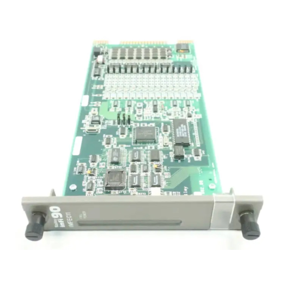
- Page 1 IMFEC11/12 ® ® Analog Input Module Process Control and Automation Solutions from Elsag Bailey Group...
- Page 2 The information contained in this document is subject to change without notice. Elsag Bailey, its affiliates, employees, and agents, and the authors and contributors to this publication specif- ically disclaim all liabilities and warranties, express and implied (including warranties of merchantability and...
- Page 3 FSK field bus mode (FSK digital data and commu- nication) and FSK analog point-to-point mode (analog inputs with or without FSK digital communication available). The IMFEC11 module can be used as a direct replacement for the IMFBS01 Field Bus Module; however, baseband communica- tions are not supported.
- Page 4 ® List of Effective Pages Total number of pages in this instruction is 53 consisting of the following: Page No. Change Date Preface Original List of Effective Pages Original iii through vii Original 1-1 through 1-8 Original 2-1 through 2-10 Original 3-1 through 3-6 Original...
-
Page 5: Table Of Contents
FUNCTIONAL OPERATION ...................2-2 Microprocessor and Control Logic Circuitry ............2-3 Module Input/Output Circuitry................2-3 Analog Inputs (Point-to-Point Mode) ..............2-4 FSK Inputs (Field Bus Mode) IMFEC11 Only ............2-5 Analog-to-Digital Converter ..................2-5 I/O Expander Bus Interface Circuitry ..............2-6 Communication Circuitry (IMFEC11 only) ..............2-7 FSK OPERATION (IMFEC11 ONLY) ................2-8 SMART TRANSMITTER....................2-8... - Page 6 Page SECTION 5 - TROUBLESHOOTING...................5-1 INTRODUCTION ......................5-1 MODULE STATUS REPORTS ..................5-1 Transmitter Status Reports (IMFEC11 ONLY) ............5-2 Missing I/O Module Error ..................5-3 Blinking Green Status LED ..................5-3 EDGE CONNECTOR PIN ASSIGNMENTS..............5-3 SECTION 6 - MAINTENANCE.....................6-1 INTRODUCTION ......................
- Page 7 FSK Signal and Decoded Digital Equivalent ............2-8 2-6. Field Bus Mode ......................2-8 2-7. FSK Analog Point-to-Point Mode ................2-10 3-1. IMFEC11/12 Switch and Jumper Locations ............3-3 4-1. Connecting the Type STT02/03 Terminal to the NTFB01 Termination Unit .....4-2 4-2. IMFEC1 Status LED ....................4-3 A-1.
- Page 8 ® Safety Summary GENERAL Equipment Environment WARNINGS All components, whether in transportation, operation or storage, must be in a noncorrosive environment. Electrical Shock Hazard During Maintenance Disconnect power or take precautions to insure that contact with energized parts is avoided when servicing. SPECIFIC Disconnect power before installing dipshunts on the module mount- WARNINGS...
- Page 9 Trademarks and Registrations Registrations and trademarks used in this document include: ® INFI 90 Registered trademark of Elsag Bailey Process Automation ® Platinum Standard Trademark of Elsag Bailey Process Automation ® IBM Registered trademark of International Business Machines Corporation WBPEEUI240756A0...
-
Page 10: Section 1 - Introduction
The IMFEC11 High Level Analog Input (FEC) module inputs 15 channels of analog or frequency shift keyed (FSK) digital sig- nals to the MFP or MFC module. The IMFEC11 module per- forms all the functions of the IMFEC12 module and also provides communication with the Bailey-Fischer &... -
Page 11: Hardware Application
HARDWARE APPLICATION The FEC module interfaces analog and digital signals from field devices to the MFP or MFC module. The IMFEC11 module can interface Bailey-Fischer & Porter FSK smart transmitters and other smart devices. The IMFEC12 is for use with conventional transmitters (BC, EQ and PT) and standard analog inputs. -
Page 12: Features
INTRODUCTION In the FSK analog point-to-point mode, the IMFEC11 module can interface up to 15 discrete analog process inputs from FSK smart devices and communicate (digitally) with those devices. Additionally, the IMFEC11 module can interface a mixture of conventional transmitters and other external analog inputs while operating in this mode. -
Page 13: How To Use This Instruction
Explains how to replace a module needing repair. Procedures Support Services Provides information about ordering parts from your local Elsag Bailey sales office. It also explains other areas of support that Elsag Bailey provides. Shows the dipshunt settings, terminal wiring for the NTAI05 Appendix A analog input termination unit and the required cabling. -
Page 14: Reference Documents
Termination module; provides input/output connection between plant equipment and the INFI 90 OPEN/Network 90 modules. Termination unit; provides input/output connection between plant equipment and the INFI 90 OPEN/Network 90 modules. REFERENCE DOCUMENTS Table lists Elsag Bailey instructions referenced in this instruction. Table 1-2. Reference Documents Number Title I-E21-56... -
Page 15: Nomenclature
Table contains the analog input module nomenclature used in this instruction. Table 1-3. Nomenclature Nomenclature Description IMFEC11 Analog input module with FSK communications for smart transmitter interface and standard analog inputs IMFEC12 Analog input module for use with conventional trans-... -
Page 16: Specifications
4 to 20 mA, 1 to 5 VDC, 0 to 1 VDC, 0 to 5 VDC, 0 to 10 VDC, -10 to +10 VDC Analog updates A/D conversions 5 times/sec FSK digital updates (IMFEC11 3 to 10 times/sec (in field bus configuration) only) A/D resolution... - Page 17 INTRODUCTION ® Table 1-5. Specifications (continued) Property Characteristic/Value Electromagnetic Compatibility Normal Test Common Mode Mode Conducted transients Pulse voltage test (1.2/50 µS) 2 kVp 1 kVp (IEC 801-5) Line frequency wave (50 Hz) 50 Vp Low voltage wave train 50 Vp (Sweep from 10 KHz to 1 MHz) Damped 1 MHz oscillatory wave 1 kVp...
-
Page 18: Section 2 - Description And Operation
(BC, EQ and PT) and standard analog inputs of 4 to 20 milliamps, 1 to 5 VDC, 0 to 1 VDC, 0 to 5 VDC, 0 to 10 VDC and -10 to +10 VDC. The IMFEC11 has all the functionality of the IMFEC12 module but also provides FSK communications for interface to Bailey-Fischer &... -
Page 19: Functional Operation
FEC module. FUNCTIONAL OPERATION The FEC module can be divided into four functional blocks for the IMFEC12 and five functional blocks for the IMFEC11. Figure shows a block diagram of the IMFEC1 Analog Input (FEC) module. -
Page 20: Microprocessor And Control Logic Circuitry
Module Input/Output Circuitry Process inputs to the IMFEC11/12 modules can be standard analog signals of four to 20 milliamps and ±10 VDC; or analog (point-to-point) or frequency shift keyed digital signals (on a field bus) (IMFEC11). -
Page 21: Analog Inputs (Point-To-Point Mode)
On-board jumpers on the IMFEC11 set the operating mode. NOTE: In field bus mode, the IMFEC11 module can handle up to 15 transmitters. The Type STT03 terminal can program a maximum of eight transmitters on a single field bus. Refer to the Smart Trans- mitter Terminal, Type STT03 instruction for more information (Table 1-2). -
Page 22: Fsk Inputs (Field Bus Mode) Imfec11 Only
DESCRIPTION AND OPERATION FSK INPUTS (FIELD BUS MODE) IMFEC11 ONLY For IMFEC11 modules in the field bus mode, all data and com- munication are FSK encoded digital signals on a shared bus and require decoding. The microprocessor can read any input by specifying the bus address of the device. -
Page 23: I/O Expander Bus Interface Circuitry
DESCRIPTION AND OPERATION ® REFERENCE FEEDBACK AND VOLTAGE ZEROING AMPLIFIER ANALOG TO DUAL SLOPE DIGITAL BUFFERS AND FILTERED INPUT INTEGRATOR/ DIFFERENTIAL OPERATION ANALOG MULTIPLEXERS DE-INTEGRATOR AMPLIFIER SELECT INPUTS MULTIPLEXER ANALOG TO ZERO-CROSSING DIGITAL DETECTOR CONTROL CHIP MICROPROCESSOR TP25185A Figure 2-4. Analog to Digital Conversion Circuitry The microprocessor signals the ADC circuitry to begin convert- ing inputs. -
Page 24: Communication Circuitry (Imfec11 Only)
DESCRIPTION AND OPERATION Communication Circuitry (IMFEC11 only) The IMFEC11 module can use FSK digital communication in the field bus mode or point-to-point mode. When the micropro- cessor enables the FSK receive gate, digital signals from an FSK style smart transmitter enter the FSK communication cir- cuitry. -
Page 25: Fsk Operation (Imfec11 Only)
Figure 2-5. FSK Signal and Decoded Digital Equivalent FSK OPERATION (IMFEC11 ONLY) The digital interface, made up of the IMFEC11 module and the controlling module, provides a communication path between an INFI 90 OPEN operator interface and Bailey-Fischer & Por- ter smart transmitters as shown in Figure 2-6. -
Page 26: Fsk Modes Of Operation (Imfec11 Only)
FSK MODES OF OPERATION (IMFEC11 ONLY) The IMFEC11 module has two operating modes: FSK field bus mode and FSK analog point-to-point mode. Mode selection is through FEC circuit board jumpers (J2 through J4). Function code 132 must be configured in the MFP or MFC device for every five analog inputs. -
Page 27: Fsk Analog Point-To-Point Mode
DESCRIPTION AND OPERATION ® Bailey-Fischer & Porter FSK style smart transmitters (Fig. 2-7). In this mode, the analog signal from each smart transmitter goes to an individual input channel (point-to-point). Because the inputs are analog point-to-point, the FEC module can interface any combination of devices while it is in this operat- ing mode. -
Page 28: Section 3 - Installation
SECTION 3 - INSTALLATION INTRODUCTION This section explains how to install the IMFEC11/12 high level analog input (FEC) module. Do not proceed with operation until reading, understanding and doing the steps in the order in which they appear. SPECIAL HANDLING Use the static grounding wrist strap when installing and remov- ing modules. -
Page 29: Unpacking And Inspection
1. Examine the module to make sure that no damage has occurred in transit. 2. Notify the nearest Elsag Bailey sales office of any damage. 3. File a claim for any damage with the shipping company that handled the shipment. -
Page 30: Dipswitch And Jumper Settings
DIPSWITCH AND JUMPER SETTINGS For the IMFEC12 module, there is one dipswitch (S1, Fig. is the same for both the IMFEC11 and the IMFEC12) that must be set before installing the module. The single dipswitch sets the I/O expander bus address. -
Page 31: Factory Test Jumper (J2)
Table shows the setting for J2. IMFEC11 Operating Mode Jumper (J3) The operating mode jumper sets the IMFEC11 operation to point-to-point mode or field bus mode. Set jumper J3 for the desired operating mode. Table lists the jumper settings. -
Page 32: Imfec11 Communication Mode Jumper (J4)
J6 through J20 and Table for jumper descriptions. If installing the IMFEC11 module in the field bus mode, the NTFB01 Field Bus Termination Unit must be used. Refer to Appendix C for information on NTFB01 configuration for field bus termination. -
Page 33: Installation
INSTALLATION ® For more information about the termination units or modules, refer to the instructions listed in Table 1-2. Installation The FEC module inserts into a standard INFI 90 OPEN module mounting unit (MMU) and occupies one slot. To install: 1. -
Page 34: Section 4 - Operating Procedures
When the IMFEC11 module detects a channel that is set up for a smart transmitter (a configuration containing function codes 132 and 133), it does a check of that channel. It reads the actual configuration of the smart transmitter and compares it to the configuration within the controlling module. -
Page 35: Operation
(reset) of the MFP or FEC module may be required for changes to take effect. For IMFEC11 modules, smart transmitter parameters can be viewed or modified using the handheld Type STT02/03 smart transmitter terminal. View only is possible when the FEC mod- ule is present and the FEC channel is on-line. -
Page 36: Status Led
OPERATING PROCEDURES STATUS LEDS The IMFEC1 module has two LEDs (red/green) on its face- plate that indicate module status. Figure shows the loca- tion of the status LEDs on the FEC faceplate. Refer to Table for a list of LED states and their meaning. B a iley IMFEC12 STATUS LED... -
Page 37: Section 5 - Troubleshooting
Corrective Action No IMFEC1 mod- Check IMFEC12 switch setting. Check ule response or IMFEC11 jumper and switch settings. wrong module type Replace the FEC module if switch and/or jumper settings check good. Check function code 132 for correct specifica- tion values, such as I/O module address. -
Page 38: Transmitter Status Reports (Imfec11 Only)
SLAVE status report) contains a smart transmitter definition function code, that status report applies to a smart transmitter connected to an IMFEC11 module. The status report will dis- play specific smart transmitter error codes when an error occurs. The status report lists the following: I/O SLAVE ERROR NUMBER (#), SLAVE ADDRESS (#), BLOCK NUM. -
Page 39: Missing I/O Module Error
TROUBLESHOOTING Missing I/O Module Error A missing I/O module error (no FEC response or wrong type) occurs when the IMFEC1 address (set by dipswitch S1 on the module) does not match the I/O module address in the control module configuration (function code 132). This error appears in the status bytes of the control module (bytes three through five). -
Page 40: P1 Edge Connector Pin Assignments
TROUBLESHOOTING ® Table 5-3. P1 Edge Connector Pin Assignments Connection Connection Connection +5 VDC Common Not used +15 VDC Not used –15 VDC Table 5-4. P2 Edge Connector Pin Assignments Connection Connection Connection Data 1 Data 5 BCLOCK Data 0 Data 4 SYNC Data 3... -
Page 41: Section 6 - Maintenance
SECTION 6 - MAINTENANCE INTRODUCTION The reliability of any stand-alone product or control system is affected by the maintenance of the equipment. Elsag Bailey recommends that all equipment users practice a preventive maintenance program that will keep the equipment operating at an optimum level. -
Page 42: Equipment And Tools Required
MAINTENANCE ® EQUIPMENT AND TOOLS REQUIRED Tools and equipment required for maintenance procedures include: Antistatic vacuum. • Clean, lint free cloth. • Compressed air. • Eberhard Faber (400A) pink pearl eraser or equivalent. • Fiberglass or nylon burnishing brush. • Foam tipped swab. -
Page 43: Printed Circuit Board Cleaning
MAINTENANCE Printed Circuit Board Cleaning Never clean electrical parts of components with live power present. Doing so exposes you to an electrical shock hazard. WARNING Wear eye protection whenever working with cleaning solvents. When removing solvents from printed circuit boards using compressed air, injury to the eyes could result from splashing solvent as it is removed from the printed circuit board. - Page 44 MAINTENANCE ® 4. Repeat with a clean cloth that is soaked with the solvent mixture. 5. Dry the edge connector contact area by wiping with a clean lint free cloth. To clean tarnished or deeply stained edge connector contacts: 1. Use an Eberhard Faber (400A) pink pearl eraser or equiva- lent to remove tarnish or stains.
-
Page 45: Section 7 - Repair And Replacement Procedures
SECTION 7 - REPAIR AND REPLACEMENT PROCEDURES INTRODUCTION This section explains the replacement steps for an IMFEC1 analog input module. There are no special tools required to replace the module. MODULE REPAIR AND REPLACEMENT If the IMFEC1 module is faulty, replace it with a new one. Do not try to repair the module;... -
Page 46: Section 8 - Support Services
SECTION 8 - SUPPORT SERVICES INTRODUCTION Elsag Bailey is always ready to assist in the operation and repair of its products. Send requests for sales or application services to the nearest sales or service office. Elsag Bailey can also provide installation, repair and maintenance contract ser- vices. - Page 47 4 to 20 milliamps, 1 to 5 VDC, 0 to 1 VDC, 0 to 5 VDC, 0 to 10 VDC and -10 to +10 VDC. NOTE: Input jumpers J6 through J20 on the IMFEC11 board must IMFEC11 Input Jumpers (J6 be set to the voltage position.
-
Page 48: Appendix A - Ntai05 Termination Unit Configuration
NTAI05 TERMINATION UNIT CONFIGURATION ® Table A-1. NTAI05 Dipshunt Settings Application/ Dipshunt Dipshunt Connecting Signal Type Configuration Locations Cable System powered XU1 to NKTU01 4 to 20 mA XU15 16 15 14 13 12 11 10 9 Externally powered 4 to 20 mA 16 15 14 13 12 11 10 9 Single-ended voltage 16 15 14 13 12 11 10 9... - Page 49 NTAI05 TERMINATION UNIT CONFIGURATION – – – – XU16 XU15 XU14 XU13 XU12 XU11 XU10 E1 (COMMON) – – – – CHASSIS TERMINAL GROUND BLOCKS E2 (+24 VDC) XU17 – – – – TERMINAL NUMBERS – – – – DIPSHUNT SOCKET (DIPSHUNT NUMBER CORRESPONDS NUMERICALLY ANALOG INPUT TO THE ANALOG INPUT NUMBER)
-
Page 50: Appendix B - Niai04 Termination Module Configuration
Table shows dipswitch settings. Figure shows FEC module to termination module cabling. NOTE: Input jumpers J6 through J20 on the IMFEC11 board must be set to the voltage position. Refer to IMFEC11 Input Jumpers (J6 through J20) in Section 3. - Page 51 NIAI04 TERMINATION MODULE CONFIGURATION ® Table B-1. NIAI04 Dipswitch Settings Dipswitch Connecting Application/Signal Type 1, 2 Configuration Cable System powered 4 to 20 mA NKTM01 or S1-S15 NKTU02 1 2 3 4 5 OPEN Externally powered 4 to 20 mA S1-S15 1 2 3 4 5 OPEN...
-
Page 52: Appendix C - Ntfb01 Termination Unit Configuration
Figure shows NTFB01 terminal assignments and Figure shows module to termination unit cabling. NOTE: Input jumpers J6 through J20 on the IMFEC11 board must be set to the voltage position. Refer to IMFEC11 Input Jumpers (J6 through J20) in Section 3. - Page 53 FBUS 15 FBUS 11 FBUS 7 FBUS 3 FBUS 12 FBUS 8 FBUS 4 T00988A Figure C-2. NTFB01 Terminal Assignments NKSL01 IMFEC11 NTFB01 T00926A Figure C-3. NTFB01 Cable Connections CONNECTING INPUTS TO THE NTFB01 TERMINATION UNIT C - 2 WBPEEUI240756A0...
- Page 54 Index Input jumpers (J6-J20) ..........3-5 Inspection..............3-2 Address selection switch (S1) ........3-3 Installation Field bus module ...........3-6 Hazardous locations..........3-2 Termination module ..........3-5 Blinking green status LED .......... 5-3 Termination unit ............3-5 Instruction ..............1-4 Contents ..............1-3 Glossary ..............1-4 Checking connections ..........6-2 Intended user ............1-1 Circuit board cleaning..........
- Page 55 ® Index (continued) NIAI04 Red/green LED............4-3 Cable connections..........B-2 Reference documents ..........1-5 Configuration ............B-1 Repair and replacement procedures ......7-1 Dipswitch settings..........B-2 Replacement parts ............. 8-1 Input circuit ............B-1 Replacing a module............ 7-1 Installation .............3-5 Terminal assignments ..........
- Page 56 Telefax 39-10-6582-941 Telephone 49-69-799-0 Telefax 65-292-9011 Telefax 49-69-799-2406 Form WBPEEUI240756A0 Litho in U.S.A. 297 Copyright © 1997 by Elsag Bailey Process Automation, As An Unpublished Work ® Registered Trademark of Elsag Bailey Process Automation ™ Trademark of Elsag Bailey Process Automation...
Need help?
Do you have a question about the IMFEC11 and is the answer not in the manual?
Questions and answers