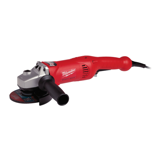
Milwaukee AG16-125XC Dissambly Instruction
Hide thumbs
Also See for AG16-125XC:
- Instructions for use manual (39 pages) ,
- Original instructions manual (33 pages) ,
- Original instructions manual (11 pages)
Advertisement
Quick Links
4939 5228 01
Special Tools
Forcing discs
Require
TX 15
Important!
Before beginning the maintenance work, perform an initial check with a high voltage test according
to VDE (see chapter Electrical and Mechanical Test Instructions).
Before all repair work, pull the power plug from the socket!
Disassembly
1
Detaching
Unscrew the handle (1).
the handle
2
Machines with QUIK-LOK: Pull off the
Quick-Lock connection cable (2).
1
Removing the
Loosen the screws (1) on both service
carbon brushes
covers (2) with TX 15.
2
Carefully lever off the service cover (2)
with aid of a screwdriver.
3
Loosen the plug contact of the carbon
brushes (3) on both sides and remove the
carbon brushes (3).
1
Detaching the
Fold away the hoop on the Fixtec nut (1)
guard cap
and unscrew the Fixtec nut (1).
2
Remove the grinding disc (2).
3
Remove the clamping flange (3).
4
Loosen three screws (4) and remove the
spring washer (5).
5
Remove the guard cap (6).
In case of stiffness, a pin-type face
spanner can be used.
4931 5990 18
4931 5990 05
1
1
2
3
6
5
4
PAGE
1
1
2
2
3
2
1
3
3
2
1
Advertisement

Summary of Contents for Milwaukee AG16-125XC
- Page 1 PAGE 4939 5228 01 Special Tools Forcing discs 4931 5990 18 Require TX 15 4931 5990 05 Important! Before beginning the maintenance work, perform an initial check with a high voltage test according to VDE (see chapter Electrical and Mechanical Test Instructions). Before all repair work, pull the power plug from the socket! Disassembly Detaching...
- Page 2 PAGE 4939 5228 01 Removing the Loosen four screws (1) on the bearing end complete spindle plate (2). assembly Remove the complete bearing end plate (2). Removing Pull off the bearing (2) from the front gear the bearing box with aid of an interior extractor (1) in direction of arrow.
- Page 3 PAGE 4939 5228 01 Removing Loosen four screws (2). the complete Remove the gear box (6) with the com- armature plete armature (4). If necessary, hit the gear box lightly with a plastic hammer to remove it. Steady the nut (3) with a fork wrench (SW12) and grasp the armature (4) care- fully with pliers (5).
- Page 4 PAGE 4939 5228 01 Machines Remove the following parts from the ar- mature (4): without – bearing sleeve (1), electronics: – press off the bearing (2), – insulating disc (3). Detaching the armature Machines with Remove the following parts from the ar- mature (5): electronics: –...
- Page 5 PAGE 4939 5228 01 Machines Remove seven screws (5) and (A) from the handle (B) and detach the handle. without electronics: Branch off the field wires (e, d, f, g) and re- move the brush holders (4) and the con- necting cables (3) and (8) from both sides.
-
Page 6: Maintenance
PAGE 4939 5228 01 Maintenance General It is recommended to submit the machine to maintenance after the carbon brushes have switched off. Cleaning Clean all parts – with the exception of the electrical parts – with cold cleaning agent. Caution! No cleaning agent should penetrate into the bearing. - Page 7 PAGE 4939 5228 01 Assembly Mounting the Insert the bearing sleeve (2) into the hous- bearing sleeve ing (1) as far as it will go. Do not pre-assemble the bearing sleeve (2) on the armature. When mounting the armature in the motor housing (1), the bearing sleeve (2) is pushed into the magnetic disc of the armature.
- Page 8 PAGE 4939 5228 01 Machines Insert the field (1) into the motor hous- ing (2). Press it in, if necessary. without electronics: Insert the mains connection cable (C) and connect the mains feed lines (a, b) (6) to the switch (9). Mounting Screw down the strain relief (7).
- Page 9 PAGE 4939 5228 01 Machines Mount the following parts on the arma- ture (1): without – insulating disc (2), electronics: – press on the bearing (3). Mounting the armature Machines with Mount the following parts on the arma- ture (1): electronics: –...
- Page 10 PAGE 4939 5228 01 Inserting Insert the completely assembled arma- the complete ture (4) into the front gear box, rotating it. armature Carefully hold the armature with pliers for support. (The armature can also be care- fully fixed in a vice provided with protective jaws.) Machines without electronics: Mag- netic disc (A) does not exist.
- Page 11 PAGE 4939 5228 01 Mounting the Insert the complete bearing end plate as- complete spindle sembly (2) in direction of arrow. assembly Fasten the bearing end plate (2) with four screws (1). Mounting the Mount the guard cap (6) and fix it with the guard cap spring washer (5) and three screws (4).
- Page 12 PAGE 4939 5228 01 Mounting Screw down the handle (1). the handle Machines with QUIK-LOK: Fasten the Quick-Lock cable (2). Test Run Test run the machine and pay attention to noises. Let the machine run-in. Electrical Test Perform an electrical test on the machine (see chapter Electrical and Mechanical Test Instructions).


Need help?
Do you have a question about the AG16-125XC and is the answer not in the manual?
Questions and answers