Table of Contents
Advertisement
Advertisement
Table of Contents

Subscribe to Our Youtube Channel
Related Manuals for TapFlo DT Series


Summary of Contents for TapFlo DT Series
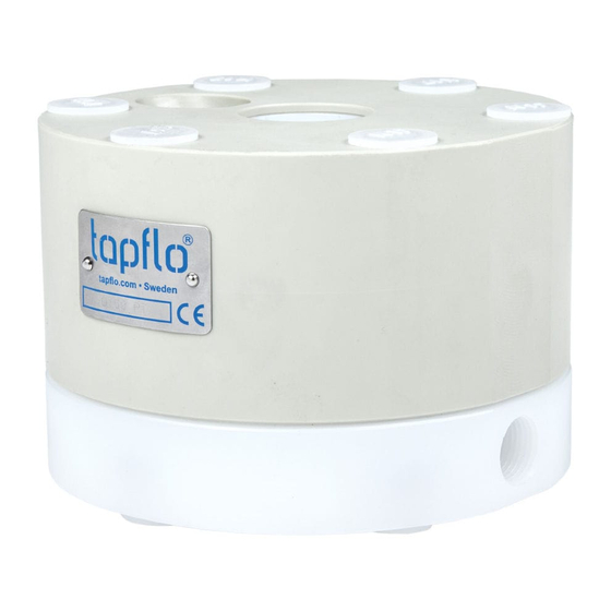
- Page 1 DT series Active Pulsation Dampener Original Instruction edition 2020 rev 1 Read this instruction manual carefully, before you install and operate the dampener. Dampener models: DT/ DTX 9/20/25/30 DT/ DTX 50/70/80 DT/ DTX 100/120/125 DT/ DTX 200/220/225 DT/ DTX 400/420/425...
-
Page 2: Table Of Contents
CONTENTS EC DECLARATION OF CONFORMITY 01/EC/DT/2016 ................4 EU DECLARATION OF CONFORMITY 01/ATEX/DT/2016 ................ 5 GENERAL ............................6 0.1. Introduction..........................6 0.2. Warning symbols ........................6 0.3. Qualification and training of personnel ................... 6 INSTALLATION ..........................7 1.1. Operation principle ........................7 1.2. - Page 3 CONTENTS OPTIONS ............................20 4.1. DTB series ..........................20 4.2. DTF series ..........................20 SPARE PARTS ..........................21 5.1. Spare parts drawing - PE & PTFE, Aluminium ............... 21 5.2. Spare parts list – PE & PTFE, Aluminium ................21 5.3.
-
Page 4: Ec Declaration Of Conformity 01/Ec/Dt/2016
Directive 2006/42/EC of European Parliament and of the Council of 17 May 2006 on machinery, • amending Directive 95/16/EC; Mr Michał Śmigiel is authorized to compile the technical file. Tapflo Sp. z o.o. ul. Czatkowska 4b 83-110 Tczew Signed for and on behalf of Tapflo AB Håkan Ekstrand... -
Page 5: Eu Declaration Of Conformity 01/Atex/Dt/2016
IIG (Gas) / IID (Dust) Equipment group: Category: Apparatus group : T4 Temperature class Signed for and on behalf of Tapflo AB Håkan Ekstrand Managing Director Tapflo AB, 16.04.2016r... -
Page 6: General
The personnel in charge of installation, operation and maintenance of the dampener we produce must be qualified to carry out the operations described in this manual. Tapflo shall not be held responsible for the training level of personnel and for the fact that they are not fully aware of the contents of this manual. -
Page 7: Installation
INSTALLATION INSTALLATION 1.1. Operation principle The pulsation dampener’s main function is to remove pressure variations on the discharge of the pump. The dampener works actively with compressed air and a diaphragm, automatically setting the correct pressure to minimise the pulsations. The air pressure supplied to the dampener is the same as the one supplied to the pump. -
Page 8: Receiving Inspection
1.4.1. Protection In the interest of health and safety it is essential to wear protective clothing and safety goggles when operating, and/or working in the vicinity of Tapflo dampeners. IOM manual active pulsation dampeners... -
Page 9: Explosion Hazardous Environments - Atex
1.4.2. Explosion hazardous environments – ATEX The standard DT series dampeners are not allowed to operate in environments where there is danger of explosion. Static electricity may occur in the dampener under operation, which may cause explosion and injury. Special conductive DTX dampeners are available for such applications. -
Page 10: Temperature Hazards
INSTALLATION 1.4.5. Temperature hazards ➢ Raised temperature can cause damage on the dampener and/or piping and may also be hazardous for personnel in the vicinity of the dampener/piping. Avoid quick temperature changes and do not exceed the maximum temperature specified when the dampener was ordered. -
Page 11: Example Of Installation
INSTALLATION 1.6. Example of installation 1.6.1. Standard pump 1.6.2. TF pump The pulsation dampener must be installed according to the sketch. It can be connected with a nipple immediately after the pump outlet, or placed independent of the pump with a flexible hose between the pump and the dampener. -
Page 12: Operation
OPERATION OPERATION 2.1. Before operating the dampener ➢ Make sure the dampener is installed according to the installation instruction. ➢ When installation is new or the dampener is reinstalled, a test run with water must be conducted to make sure that the dampener operates normally and does not leak. ➢... -
Page 13: Maintenance
MAINTENANCE MAINTENANCE 3.1. When the dampener is new or reassembled If the dampener is new or reassembled after maintenance it is important to retighten the dampener housing nuts (pos. 37) after a week of operation. Make sure to use the right torque – see chapter 6.2. “Tightening torques”. 3.2. -
Page 14: Location Of Faults
MAINTENANCE 3.4. Location of faults PROBLEM POSSIBLE FAULT POSSIBLE SOLUTION The air pressure is to low Check if set pressure equals set pressure for the pump The dampener does not The air connection is blocked Check / clean air supply connection work Muffler is blocked Check / clean / replace muffler... -
Page 15: Disassembly Of The Dampener
MAINTENANCE 3.5. Disassembly of the dampener The numbers put in brackets, refer to the part numbers in the spare part drawings and spare part lists in chapter 5 “Spare parts”. 3.5.1. Before the disassembly procedure Be sure to drain all liquid from the dampener. Cleanse or neutralize the thoroughly. Disconnect the air supply and then the inlet and outlet. - Page 16 MAINTENANCE Fig. 3.5.5 Take the pin screws [14] out of the dampener housing [11]. Fig 3.5.6 Unscrew the diaphragm [15] by hand (clockwise). Fig 3.5.7 Using an Allen key, unscrew the shaft ending [1652] from the diaphragm. Fig 3.5.8 Push out the shaft [1651] from the dampener housing Fig 3.5.9 Check the inner seals [36] and O-rings [47].
-
Page 17: Assembly Of The Dampener
MAINTENANCE 3.6. Assembly of the dampener The assembly procedure is done in the reverse order to the disassembly. Nevertheless there are a few things that you have to remember in order to assemble the dampener correctly. Fig. 3.6.1 Using a screwdriver, insert the O-rings [47] into the dampener block [12]. - Page 18 MAINTENANCE Fig. 3.6.6 Push the diaphragm [15] in, so that it is touching the dampener block [12]. Fig. 3.6.7 Put the pin screws [14] and washers [38] into the dampener housing [11]. Fig. 3.6.8 Screw the nuts [37] onto the pin screws [14] so that ca.
-
Page 19: Test Run
MAINTENANCE Fig. 3.6.12 Insert the nut covers [579] on both sides of the dampener. Fig. 3.6.13 Insert the muffler [25] and the circlip [27] in a circular manner. 3.6.1. Test run We recommend you to conduct a test of the dampener before installing it in the system, to detect if there is no air leakage through diaphragm shaft. -
Page 20: Options
OPTIONS 4. OPTIONS 4.1. DTB series The DTB series equipped with fully pneumatic control system “Guardian” is perfect choice when the diaphragm rupture has to be immediately detected in order to avoid product leak to the environment. When rupture is detected the pump is automatically stopped and an alarm can be generated. -
Page 21: Spare Parts
SPARE PARTS 5. SPARE PARTS 5.1. Spare parts drawing - PE & PTFE, Aluminium 5.2. Spare parts list – PE & PTFE, Aluminium Pos. Q-ty Description Material Dampener housing PE, PTFE, Aluminium Threaded insert 4/6***** Reinforcement plate 1173 1*** AISI 316L Cover 1181 1***... -
Page 22: Spare Parts Drawing - Stainless Steel Industrial And Sanitary
SPARE PARTS 5.3. Spare parts drawing – Stainless steel industrial and sanitary 5.4. Spare parts list – steel and sanitary Pos. Q-ty Description Material Dampener housing AISI 316L Dampener block Pin screw 4/6/8* A4-80 Diaphragm EPDM, PTFE, NBR, FKM Shaft 1651 AISI 316L Shaft ending... -
Page 23: Stocking Recommendation
5.6. How to order parts When ordering spare parts for Tapflo dampeners, please let us know what is the model number (see nameplate) and serial number (visible on nameplate and stamped on the top or on the side [DTF version] of the dampener block). Then just indicate the part numbers from the spare parts list and quantity of each item. -
Page 24: Data
DATA DATA 6.1. Overall dimensions Dimensions in mm (where other is not indicated) Dimensions in inch (where other is not indicated) General dimensions only, ask us for detailed drawings. Changes reserved without notice. IOM manual active pulsation dampeners... -
Page 25: Dimensions Table - Plastic (Pe&Ptfe)
DATA 6.1.1. Dimensions table – Plastic (PE&PTFE) Plastic dampeners – PE & PTFE series DIMENSION DT9/20 DT50 DT100 DT200 DT400 DT800 G 3/8” G 1/2" G 1" G 1.1/2" G 2" DIN Flange DN15 DN15 DN25 DN40 DN50 DN80 ANSI Flange 1/2"... -
Page 26: Dimensions Table - Metal Series (Aluminium)
DATA 6.1.2. Dimensions table – Metal series (aluminium) Metal dampeners – Aluminium series DIMENSION DT25 A DT70 A DT120 A DT220 A DT420 A DT820 A G 1/2” G 3/4" G 1" G 1.1/2" G 2" G 3” DIN Flange DN15 DN20 DN25... - Page 27 DATA IOM manual active pulsation dampeners...
-
Page 28: Dimensions Table - Metal Series (Stainless Steel)
DATA Dimensions table – Metal series (Stainless Steel) 6.1.3. Metal dampeners – Stainless steel series (industrial) DIMENSION DT70 S DT120 S DT220 S DT420 S DT820 S G 3/4" G 1" G 1.1/2" G 2" DIN Flange DN20 DN25 DN40 DN50 DN80 ANSI Flange... -
Page 29: Dimensions Table - Sanitary Series
DATA Dimensions table – Sanitary series 6.1.4. Metal dampeners – Stainless steel series (hygienic) DIMENSION DT30 S DT80 S DT125 S DT225 S DT425 S DT825 S Tri-clamp 76.1 DIN thread DN20 DN25 DN40 DN50 DN65 DN80 SMS thread 63.5 76.1 RJT thread 3/4"... -
Page 30: Tightening Torques
DATA 6.2. Tightening torques The following tightening torques are recommended. Grub screw pos. 1651 [Nm] DAMPENER SIZE Pin screw pos.14 [Nm] DT 9/20/25/30 DT 50/70/80 DT 100/120/125 DT 200/220/225 DT 400/420/425 DT 800/820/825 For routine inspection and maintenance schedule see chapter 3.2. “Routine inspection” and 3.3. - Page 31 DATA DAMPENER SIZE TECHNICAL DATA DT30 DT80 DT125 DT225 DT425 DT825 Max air pressure [bar] / [psi] 90 / 90 / 90 / 90 / 90 / 90 / Max temp. with EPDM [°C] / [°F] 70 / 70 / 70 / 70 / 70 /...
-
Page 32: Warranty
WARRANTY WARRANTY 7.1. Warranty form Company: Telephone: Fax: Address: Country: Contact Name: E-mail: Date of dampener Delivery Date: installation: Dampener type: Serial No (see name plate or stamped on dampener housing): Description of the fault: The installation: Liquid: Temperature [°C]: Viscosity [cPs]: Spec grav. -
Page 33: Returning Parts
7.3. Warranty Tapflo warrants products under conditions as stated below for a period of not more than 5 years from installation and not more than 6 years from date of manufacturing. 1. The following terms and conditions apply to the sale of machinery, components and related services and products, of Tapflo (hereinafter “the products”). - Page 34 9. Tapflo will not be liable on any claim, whether in contact, tort, or otherwise, for any indirect, special, incidental, or consequential damages, caused to the customer or to third parties, including loss of profits, arising by any possible infringement of par.
Need help?
Do you have a question about the DT Series and is the answer not in the manual?
Questions and answers