
Related Manuals for Kato Imer CARRY 107


Summary of Contents for Kato Imer CARRY 107
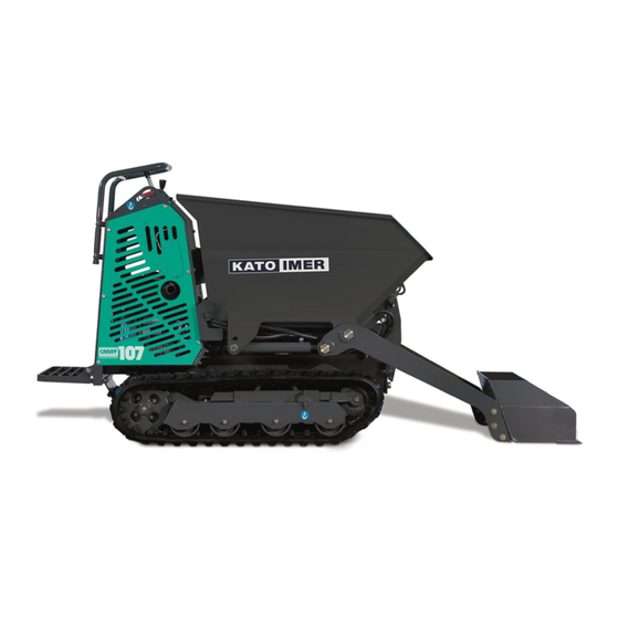
- Page 1 OPERATING INSTRUCTIONS TRACKED MINIDUMPER CARRY 107 • 107-E serial numbers from nr.: CARRY 107 MC*00430 CARRY 107-E MC*00430 (Original instructions) 03/17 – R00 Code 2050207044...
-
Page 3: Table Of Contents
CONTENTS ROUTINE MAINTENANCE PREFACE SAFETY INFORMATION SAFETY MEASURES ....................1 GENERAL ............................... 1 USE OF THE MACHINE ......................... 2 DRIVING SAFETY ..........................3 LOADING AND TRANSPORT ........................ 3 PARKING ..............................4 SERVICE ..............................4 SAFETY LABELS AND SIGNS ......................6 INSTRUCTIONS FOR USE ................... - Page 4 MAINTENANCE ......................28 MAINTENANCE INTERVALS ......................28 RECOMMENDED LUBRICANT TABLE ....................28 WHEN REQUIRED MAINTENANCE AND CHECKS ................29 3.3.1 CHECKING THE TRACK TENSION ......................29 3.3.2 TRACK TENSION ADJUSTMENT ........................ 29 3.3.3 RUBBER TRACK SHOE MAINTENANCE ....................29 3.3.4 BATTERY MAINTENANCE ...........................
- Page 5 KATO IMER S.p.A. 3) Indirizzo: località CUSONA - 53037 SAN GIMIGNANO (SI) - ITALY File tecnico compilato da: Direttore tecnico KATO IMER S.p.A. Indirizzo: località CUSONA - 53037 SAN GIMIGNANO (SI) - ITALY 6) Dichiara che la macchina categoria: CRAWLER COMPACT...
- Page 6 (Direktive 2006/42/EG, Nachtrag II, 1A) Manufacture: Hersteller: Address: Adresse: Technical file compiled by: KATO IMER S.p.A. Technical department manager Technische Datei erstellt von: Technischer Leiter KATO IMER S.p.A Address: Adresse: Hereby we declare that the machine category: DUMPER. Erklärt hiermit, dass die Maschine-Kategorie: TRANSPORTER.
- Page 7 SVENSKA (översättning) EG-FÖRSÄKRAN OM ÖVERENSSTÄMMELSE (Direktiv 2006/42/EC , Annex II, 1A) Tillverkare: Adress: Den tekniska filen har ifyllts av: den tekniska chefen vid KATO IMER S.p.A Adress: Det intygas att maskinen i kategorin: GRÄVSKOPA FÖR LASTNING Typ: Serienummer: Installerad nettoeffekt (kW/rpm): Överensstämmer med kraven i maskindirektivet 2006/42/EG, med ändringar, samt med den...
- Page 8 SCHEDULED MAINTENANCE Correct maintenance is essential to warrant long life of the machine in peak conditions. This is why KATO IMER has scheduled a series of checks and operations to be carried out c/o authorised service centres. WARNING: The scheduled Maintenance coupons are specified by the Manufacturer. The failure to perform them may invalidate the guarantee.
-
Page 9: Preface
’ HE MACHINE S COMPONENTS AND SPECIFICATIONS ARE SUBJECT TO CHANGE WITHOUT NOTICE • AKE SURE THAT THE SUPPLIED OPERATING MANUAL CORRESPONDS TO THE FEATURES OF THE KATO IMER MACHINE IN CASE OF DOUBT CONTACT ASSISTANCE SERVICE • KATO IMER... -
Page 10: Safety Measures
MINIDUMPER SAFETY CARRY 107 SAFETY MEASURES GENERAL WARNING EFORE USING THE MACHINE MOVE AWAY EVERYONE NEARBY 1. MAKE SURE YOU HAVE READ AND UNDERSTOOD THE INSTRUCTIONS AND WARNINGS This manual, the nameplates and labels on the machine provide the information required for correct and safe operation of the machine. -
Page 11: Use Of The Machine
MINIDUMPER SAFETY CARRY 107 MAINTAIN GOOD VENTILATION Do not use the machine for indoor works. Take all precautions to vent exhaust gas externally before starting the engine if working in a hole in the ground, tunnel or trench. In such a place, the air trends to stagnate. -
Page 12: Driving Safety
MINIDUMPER SAFETY CARRY 107 DRIVING SAFETY 1. WORKING MANEUVERS In normal conditions (not emergency) ALWAYS steer as slowly as possible. Steering jerkily or while stationary reduces the service life of the machine and its tracks. Steer slowly so as not to overload the drive wheels, especially on uneven or sloping ground. -
Page 13: Parking
MINIDUMPER SAFETY CARRY 107 PARKING WARNING F PARKED ON SLOPING GROUND OR WHEN THE MACHINE IS OUT OF SERVICE ALWAYS ENGAGE THE PARKING BRAKE F THE MACHINE IS TO BE PARKED FOR A LONG TIME ON VERY SLOPING GROUND CHOCK THE WHEELS WITH ADDITIONAL CHOCKS 1. - Page 14 MINIDUMPER SAFETY CARRY 107 5. ELECTROLYTIC BATTERY MAINTENANCE Do not touch the internal battery elements. Battery acid burns the skin and can cause blindness if it is splashed into the eyes. In the event of contact with the acid, rinse the skin contacted with lots of water.
-
Page 15: Safety Labels And Signs
MINIDUMPER SAFETY CARRY 107 SAFETY LABELS AND SIGNS The machine bears a variety of safety signs and labels. This section indicates where they are located and the respective hazards. Make sure that all safety labels are legible. Clean and replace damaged and illegible signs. -
Page 16: Instructions For Use
MINIDUMPER INSTRUCTIONS FOR USE CARRY 107 INSTRUCTIONS FOR USE MACHINE CONTROLS > > >... -
Page 17: Machine Travel (Levers A And B)
MINIDUMPER INSTRUCTIONS FOR USE CARRY 107 Trasferimento 2.1.1 MACHINE TRAVEL (Levers A and B) in avanti LEVA "B" Move the lever of number’s setting of engine revolutions in the desired position. Check right and left travel levers as follows: LEVA "A"... -
Page 18: Double Speed (Lever C)
MINIDUMPER INSTRUCTIONS FOR USE CARRY 107 LEVER "C" 2.1.2 DOUBLE SPEED (Lever C) Double Single speed travel s peed Pull the lever backwards to move at single speed. Use single speed on rough Single ground or soft surfaces. Single speed is also recommended when loading and speed unloading the machine from carrier transport. -
Page 19: Use Of The Engine
MINIDUMPER INSTRUCTIONS FOR USE CARRY 107 2.2 USE OF THE ENGINE CHECKS BEFORE STARTING THE ENGINE. Check the levels of the hydraulic oil, engine oil and fuel. For the checking methods, refer to the “Daily checks” section of this manual. -
Page 20: Starting Of Diesel Engine
MINIDUMPER INSTRUCTIONS FOR USE CARRY 107 2.2.3 STARTING OF DIESEL ENGINE 1. Check that diesel cock, under the tank, is opened. 2. Put the accelerator lever (E) in the intermediate position. 3. Turn the key (I) in “ON” position. The indicators (N) “oil... -
Page 21: Lifting The Machine
MINIDUMPER INSTRUCTIONS FOR USE CARRY 107 2.4 LIFTING THE MACHINE WARNING • SE APPROPRIATE CABLES AND TOOLS FOR LIFTING IFTING CABLES MUST HAVE SUFFICIENT LENGTH TO AVOID CONTACT WITH THE MACHINE • SE HOISTING EQUIPMENT ABLE TO SUPPORT THE WEIGHT OF THE MACHINE •... -
Page 22: Attachments
MINIDUMPER INSTRUCTIONS FOR USE CARRY 107 2.6 ATTACHMENTS BUCKET WITH SHOVEL BUCKET CONCRETE MIXER KIT CONCRETE MIXER KIT WITH SHOVEL PLATFORM GRADER BLADE KIT... -
Page 23: Accessories And Their Use
MINIDUMPER INSTRUCTIONS FOR USE CARRY 107 2.7 ACCESSORIES AND THEIR USE 2.7.1 BUCKET The 0.33 m bucket is the most suitable accessory for carrying debris, earth, sand, gravel, miscellaneous aggregates, conglomerates, concrete, lime and in any case all materials that may be used for site activities. The bucket can be combined with the self-loading shovel. -
Page 24: Concrete Mixer Kit
MINIDUMPER INSTRUCTIONS FOR USE CARRY 107 2.7.4 CONCRETE MIXER KIT Concreting kit consists of a 250 lt. mixing vat, operated by an oleo dynamic motor. It is suitable to mix building conglomerate, concrete or lime; composite mould or similar in seedling nursery field; fodder and similar in agricultural field. -
Page 25: Grader Blade User Instructions (Optional Accessory)
MINIDUMPER INSTRUCTIONS FOR USE CARRY 107 2.7.8 GRADER BLADE USER INSTRUCTIONS (OPTIONAL ACCESSORY) • Make sure the blade is secured against the rocker by fitting the pins (B) into the holes (1). Adjust the height of the blade with lever F (ref. § 2.1). -
Page 26: Instructions For Self-Loading Shovel Assembly. (Optional)
MINIDUMPER INSTRUCTIONS FOR USE CARRY 107 2.7.10 INSTRUCTIONS FOR SELF-LOADING SHOVEL ASSEMBLY. (OPTIONAL) L.1300 L.930 L.1500 L.1100 Fit the union tees (A) on the cylinders. Right-hand cylinder with union on bottom connector, left-hand cylinder with union on top connector. Insert the steel bushings (B) in the bucket and fit the greasing nipple (C). WARNING use special tools to insert the bushings. -
Page 27: Assembly Instructions For Concrete Mixing Kit Self-Loading Shovel. (Opt.)
MINIDUMPER INSTRUCTIONS FOR USE CARRY 107 2.7.11 ASSEMBLY INSTRUCTIONS FOR CONCRETE MIXING KIT SELF-LOADING SHOVEL. (OPT.) 1) Remove the protective cover from the concrete mixing kit control panel and disconnect the pipe (1) from the union tee. 2) Assemble the arm and cylinder on the concrete mixer frame using the special pins and screws. -
Page 28: Installing The Hi Flow Auxiliary Pto. (Optional)
MINIDUMPER INSTRUCTIONS FOR USE CARRY 107 2.7.12 INSTALLING THE HI FLOW AUXILIARY PTO. (OPTIONAL) Remove the front housing on the bin side, and unscrew the oil filler cap to depressurise the hydraulic circuit. Mount fittings (3) and (4) to the hydraulic junction (1). Fit the hydraulic junction to its mounting point with the bracket (2) and the provided bolts, washers and nuts. -
Page 29: Replacement Procedure Of Accessories
MINIDUMPER INSTRUCTIONS FOR USE CARRY 107 REPLACEMENT PROCEDURE OF ACCESSORIES 2.8.1 PROCEDURE OF RELEASE-LINK-UP OF ACCESSORIES WARNING N ORDER TO AVOID ACCIDENTS PARTICULARLY WHEN THERE ARE FORCED LOCKING WE ADVISE TO USE THE KEY – TO PROCEED WITH RELEASE LINK UP OF ACCESSORIES The unhook of accessory can be done by means a supplied key. -
Page 30: Instructions For Bucket Lifting With Shovel Or Concrete Mixer Kit
MINIDUMPER INSTRUCTIONS FOR USE CARRY 107 2.8.3 INSTRUCTIONS FOR BUCKET LIFTING WITH SHOVEL OR CONCRETE MIXER KIT USE STEEL CABLES WITH MINIMUM CAPACITY of 300 Kg. BUCKET WITH SHOVEL TO LIFT THE BUCKET WITH SHOVEL, HOOK THE LIFTING CABLES AT POINTS (A) AND (B). -
Page 31: Instructions For Accessory Release By Using Lifting Jack
MINIDUMPER INSTRUCTIONS FOR USE CARRY 107 2.8.4 INSTRUCTIONS FOR ACCESSORY RELEASE BY USING LIFTING JACK RAISE THE SHOVEL TO OVERTURN THE ACCESSORY THE END OF ITS STROKE AND DISCONNECT THE FLUID POWER PIPES THROUGH THE SPECIAL QUICK COUPLINGS. LOWER THE ACCESSORY COMPLETELY. -
Page 32: Instructions For Accessory Link-Up By Using Lifting Jack
MINIDUMPER INSTRUCTIONS FOR USE CARRY 107 2.8.5 INSTRUCTIONS FOR ACCESSORY LINK-UP BY USING LIFTING JACK CAREFULLY APPROACH THE GANTRY RAISE THE BOOM FRAME KEEPING CENTRED WITH UNTIL COUPLING THE STRUCTURE. THE ACCESSORY. RAISE THE ACCESSORY MOVE BACKWARDS SLOWLY UNTIL TO RELEASE THE THE ACCESSORY RESTS ON RESTING PINS. -
Page 33: Instructions For Concrete Mixer Kit Release By Using Lifting Jack
MINIDUMPER INSTRUCTIONS FOR USE CARRY 107 2.8.6 INSTRUCTIONS FOR CONCRETE MIXER KIT RELEASE BY USING LIFTING JACK RAISE THE SHOVEL TO THE RAISE THE ACCESSORY, RELEASE THE TWO PIPE END OF ITS STROKE. STOPPER BRACKETS FROM THE MACHINE FRAME AND LOWER THE ACCESSORY. -
Page 34: Instructions For Concrete Mixer Kit Link-Up By Using Lifting Jack
MINIDUMPER INSTRUCTIONS FOR USE CARRY 107 2.8.7 INSTRUCTIONS FOR CONCRETE MIXER KIT LINK-UP BY USING LIFTING JACK CAREFULLY APPROACH THE RAISE THE BOOM FRAME GANTRY KEEPING CENTRED UNTIL COUPLING WITH THE STRUCTURE. THE ACCESSORY. RAISE THE ACCESSORY MOVE BACKWARDS SLOWLY UNTIL... -
Page 35: Instructions For Grader Blade Kit Release
MINIDUMPER INSTRUCTIONS FOR USE CARRY 107 2.8.8 INSTRUCTIONS FOR GRADER BLADE KIT RELEASE POSIZIONARE LA MACCHINA SU TERRENO SOLIDO E PIANEGGIANTE. SGANCIARE IL SISTEMA DI BLOCCAGGIO DELL'ACCESSORIO E POSITION THE MACHINE ON SOLID, FLAT TERRAIN AND RAISE RELEASE THE TOOL LOCKING SYSTEM AND SLOWLY... -
Page 36: Precautions For Using Rubber Track Shoes
MINIDUMPER INSTRUCTIONS FOR USE CARRY 107 2.9 PRECAUTIONS FOR USING RUBBER TRACK SHOES RUBBER TRACK SHOE STRUCTURE WARNING F A CRACK IN THE RUBBER REACHES THE STEEL CORD IT MAY BE RUSTED AND CUT HEN ANY CRACK IS DETECTED REPAIR IT IMMEDIATELY WITH... -
Page 37: Maintenance
MINIDUMPER MAINTENANCE CARRY 107 3 MAINTENANCE 3.1 MAINTENANCE INTERVALS Check point Item When required Tracks Check and ad just tension Battery Cleaning and level check of electrolytic liquid Gears with greaser Grease lubrication Daily (every 8 hours of work) Engine Oil... -
Page 38: When Required Maintenance And Checks
MINIDUMPER MAINTENANCE CARRY 107 3.3 WHEN REQUIRED MAINTENANCE AND CHECKS 3.3.1 CHECKING THE TRACK TENSION When the track or tracks rub heavily against the structure that carries the actual track, checking the tension is necessary. 3.3.2 TRACK TENSION ADJUSTMENT Remove the protective cover (A) loosening the M8 screw,... -
Page 39: Battery Maintenance
MINIDUMPER MAINTENANCE CARRY 107 3.3.4 BATTERY MAINTENANCE WARNING • B ATTERY GIVE OFF FLAMMABLE FUMES THAT CAN EXPLODE • D O NOT SMOKE WHEN OBSERVING THE BATTERY ELECTROLYTE LEVELS • E LECTROLYTE IS AN ACID AND CAN CAUSE PERSONAL INJURY IF IT CONTACTS SKIN OR EYES •... -
Page 40: Daily Checks And Maintenance
MINIDUMPER MAINTENANCE CARRY 107 3.4 DAILY CHECKS AND MAINTENANCE DANGER • C HECK OIL LEVEL WITH THE ENGINE OFF EVER CHECK THE OIL LEVEL WITH THE ENGINE RUNNING • T O AVOID ENGINE PROBLEMS NEVER EXCEED THE MAXIMUM OIL LEVEL... -
Page 41: Walk-Around Inspection
MINIDUMPER MAINTENANCE CARRY 107 3.4.4 WALK-AROUND INSPECTION 1. Check the correct tightening of the accessory coupling system. 2. Inspect the loose bolts. Tighten any loose bolts. Repair if necessary. 3. Inspect any cracks in cylinder mounting brackets. Repair if damaged. -
Page 42: Air Filtering Element Replacement
MINIDUMPER MAINTENANCE CARRY 107 3.6.3 AIR FILTERING ELEMENT REPLACEMENT Refer to the instructions of the engine handbook for air filtering element replacement operations. 3.6.4 HYDRAULIC SYSTEM STRAINER REPLACEMENT The strainer is located under cylinder of lifting tool holder. 1. Raise the tool holder and switch off the engine. -
Page 43: Unusual Operating Conditions
MINIDUMPER MAINTENANCE CARRY 107 3.8 UNUSUAL OPERATING CONDITIONS Special problems in maintenance and operation are caused by unusual conditions such as extremes in heat, cold and humidity, high altitude, salt water, and dusty or sandy work sites. When operating under such conditions, special precautions must be taken to prevent machine damage, minimize wear, and avoid component deterioration. -
Page 44: Long Time Storage
MINIDUMPER MAINTENANCE CARRY 107 The fuel system should be kept free of sand and dust by keeping the tank filler cap tight and servicing the fuel filters frequently. The engine breathers and air cleaner should also be serviced frequently to prevent sand and dust from entering the engine. -
Page 45: Trouble Shooting
MINIDUMPER TROUBLE SHOOTING CARRY 107 TROUBLE SHOOTING 4.1 TROUBLE AND REMEDIES Note any occurrence unusual in normal machine operation during daily operations. For every fault detected, try to investigate the causes, and act promptly. If unusual occurrences are overlooked due to neglect, more serious problems may arise later. -
Page 46: Hydraulic System
MINIDUMPER HYDRAULIC SYSTEM DIAGRAM CARRY 107 HYDRAULIC SYSTEM 5.1 TECHNICAL DATE Hydraulic oil tank capacity 16 litres REF. DESCRIPTION PRESSURE Hydraulic oil system capacity 22 litres Kgf/cm Pump flow rate P1-P2-P3: 3x14 litres/min. MR1 Main pump max. pressure valve P1 13,7 POWER TAKE-OFF. -
Page 47: Hydraulic System Diagram 5 Elements
MINIDUMPER HYDRAULIC SYSTEM DIAGRAM CARRY 107 5.3 HYDRAULIC SYSTEM DIAGRAM 5 ELEMENTS The 5-element control valve is used: In the version with fixed track, loading bucket, dumper or deck and with the possibility of installing the loader shovel or another attachment that needs power take-off. -
Page 48: Hydraulic System Diagram 6 Elements
MINIDUMPER HYDRAULIC SYSTEM DIAGRAM CARRY 107 5.4 HYDRAULIC SYSTEM DIAGRAM 6 ELEMENTS The 6-element control valve is used: In the version with extensible track, with loading bucket, dumper or deck and with the possibility of installing the loader shovel or another attachment that needs power takeoff. -
Page 49: Technical Data
MINIDUMPER SPECIFICATIONS CARRY 107 TECHNICAL DATA 6.1 GENERAL SPECIFICATIONS GENERAL MACHINE PERFORMANCE RATES Travel speed km / h 2,3-3,2 Gradeability 36% (20°) % (°Deg.) Gradeability with load % (°Deg.) 20% (11°) Capacity Operating temperature range -20 / +46 °C WEIGHT... -
Page 50: Level Of Exposure To Vibrations
MINIDUMPER SPECIFICATIONS CARRY 107 6.4 LEVEL OF EXPOSURE TO VIBRATIONS ( DIRECTIVE 2002/44/CE ) Unit Whole-body Hand / Arm Daily exposure action value m/sec² Daily exposure limit value m/sec² 1,15 Equivalent acceleration - For whole-body vibrations (Method of measurement according to ISO2631 ) -
Page 51: Overall Dimensions
MINIDUMPER SPECIFICATIONS CARRY 107 6.5 OVERALL DIMENSIONS BUCKET + SHOVEL CONCRETE MIXER + SHOVEL PLATFORM GRADER BLADE... - Page 52 TRACKED MINIDUMPER CARRY 107 PUBLISHED: MARCH 2017 KATO IMER S.p.A. ITALY...
Need help?
Do you have a question about the CARRY 107 and is the answer not in the manual?
Questions and answers