Table of Contents
Advertisement
Quick Links
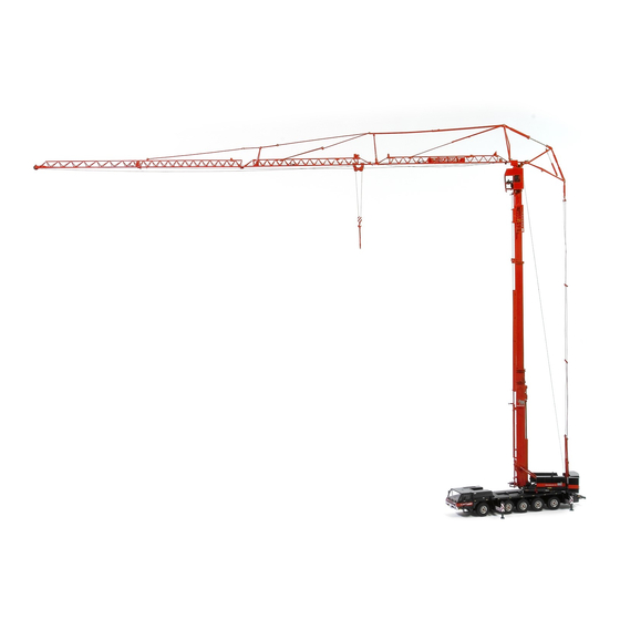
SK599-AT5
Introduction
Truck
Introduction
Dear user,
This manual provides the user of the Spierings folding crane SK599-AT5 with information concerning the truck's
construction, function and operation. Also detailed, technical descriptions and maintenance instructions are given in
the maintenance section of this manual.
SPIERINGS MOBILE CRANES
P.O. Box 24
5340 AA OSS
The Netherlands
Merwedestraat 15
5347 KZ OSS
The Netherlands
Fax +31 412 67 12 20
Phone number daytime:
Phone number evening time:
www.spieringscranes.com
© 2014 Copyright Spierings Mobile Cranes. All rights reserved.
No part of this publication may be reproduced or published, in any form or in any way, by print, photo print, microfilm or any other
means without prior permission from the manufacturer.
+31 412 69 77 77
+31 655 78 24 85
SPIERINGS MOBILE CRANES USER MANUAL V 0.1
Advertisement
Table of Contents

Related Manuals for SPIERINGS SK599-AT5


Summary of Contents for SPIERINGS SK599-AT5
- Page 1 Truck Introduction Dear user, This manual provides the user of the Spierings folding crane SK599-AT5 with information concerning the truck’s construction, function and operation. Also detailed, technical descriptions and maintenance instructions are given in the maintenance section of this manual.
-
Page 2: Liability Clause
If at any work site of the Spierings truck/crane the safety rules and regulations are more strict than those laid down in the manual, or possible additions thereto, these stricter rules are to be complied with under penalty of expiry of the guarantee and with exclusion of every liability. -
Page 3: Explanation Of The Used Symbols
Do not come in turning radius! Wear safety shoes! Corrosive substances! Electric voltage! Wear a helmet! Wear a safety harness! Environmental hazard! Check / test! Caution! Incorrect! Danger of slipping! Good! Entrapment hazard! Conditions Fire hazard! SPIERINGS MOBILE CRANES USER MANUAL V 0.1... -
Page 4: Table Of Contents
3.3. Wing mirrors .............................. 3-5 3.4. Sun blinds ..............................3-5 3.5. Storage room ............................. 3-5 3.6. Battery chargers remote control batteries ....................3-6 3.7. Windscreen washer reservoir ........................3-7 3.8. Fire extinguisher ............................3-7 SPIERINGS MOBILE CRANES USER MANUAL V 0.1... -
Page 5: Table Of Contents
4.5. Switching gears ............................4-12 4.5.1. Gear lever ............................. 4-13 4.5.2. Rotary switch ..........................4-14 4.5.3. Automatic mode ........................... 4-15 4.5.4. Manual mode ..........................4-16 4.6. Driving off ..............................4-17 4.7. Driving backwards ........................... 4-18 SPIERINGS MOBILE CRANES USER MANUAL V 0.1... - Page 6 4.17.3.1. Remove drive shafts on output shafts of the transfer case .......... 4-64 4.17.3.2. Power-assisted steering ....................4-64 4.17.4. Towing with damage to the transfer case ..................4-65 4.17.5. Towing with damage to the driven axles..................4-65 SPIERINGS MOBILE CRANES USER MANUAL V 0.1...
- Page 7 Table of contents Truck Maintenance truck .............................. 5-1 5.1. When is the right time to thoroughly inspect your Spierings crane? ............5-1 5.1.1. Electronic component ........................5-1 5.1.2. Drive component of the crane ......................5-1 5.1.3. Jib sections and towers ........................5-2 5.1.4.
- Page 8 10.2.2. Topping up oil diesel engine truck ....................10-4 10.2.3. Refreshing oil diesel engine truck ....................10-5 10.2.3.1. Draining oil ........................10-5 10.2.3.2. Replacing oil filter element................... 10-6 10.2.3.3. Topping up oil ......................10-6 VIII SPIERINGS MOBILE CRANES USER MANUAL V 0.1...
- Page 9 11.4.4. Checking oil level axle hubs ....................... 11-11 11.4.5. Refreshing oil axle hubs ......................11-12 11.5. Tyres ..............................11-13 11.5.1. General maintenance ......................... 11-13 11.5.2. Tyre pressure ..........................11-13 11.6. Brake linings ............................11-14 11.6.1. Checking brake linings ....................... 11-14 SPIERINGS MOBILE CRANES USER MANUAL V 0.1...
- Page 10 14.2.3. Specifications axles / brakes / tyres ..................... 14-2 14.3. Specifications electric system truck ......................14-3 14.4. Specifications hydraulic system truck ...................... 14-3 14.5. Specifications pneumatic system truck ....................14-3 14.6. Specifications lubricants truck ......................... 14-3 15. Annexes ................................15-1 SPIERINGS MOBILE CRANES USER MANUAL V 0.1...
-
Page 11: General Data
Truck General data The AT5 carriage is especially designed for the Spierings SK599 folding crane. Extra attention is paid to a safe and comfortable transport to the work site. The crane is suited for driving on public roads, fully equipped with counterweight and tools. The chassis is a specially rigid structure to create a good crane support. -
Page 12: Steering
Retarder; • Optional: connection air braked trailer. 1.6. 4-Point outrigger system • Full outrigger support base (wide): 7.50 m x 7.66 m; • Reduced outrigger support base (narrow): 7.50 m x 5.72 m. SPIERINGS MOBILE CRANES USER MANUAL V 0.1... - Page 13 However, for Spierings cranes it is not the chassis number that is needed. ITS needs the engine number, which is listed on the UPEC chart and can be found underneath the cover plate of the central console in the truck cabin.
- Page 14 SK599-AT5 General data Truck SPIERINGS MOBILE CRANES USER MANUAL V 0.1...
-
Page 15: Introduction To The Truck
Side view camera (optional) (see § 2.11. Side view camera (optional); M. Buffer beam; N. Storage box steel support partitions (see § 2.7. Storage box); O. Reverse drive camera (see § 2.10. Reverse drive camera). SPIERINGS MOBILE CRANES USER MANUAL V 0.1... -
Page 16: Keys
(Sliding) doors rear toolbox; Removable cover plates engine cowling; Cross key engine cowling crane: Doors engine cowling crane; Cross key control cabinet truck: Control cabinet truck (for the benefit of suspension system and outrigger base). SPIERINGS MOBILE CRANES USER MANUAL V 0.1... -
Page 17: Truck Cab
Co-driver’s seat (see § 3.2. Seats); M. Fire extinguisher (see § 3.8. Fire extinguisher); N. Central console (see § 2.3.2. Central console); O. Cup holder; P. Main switch truck (see § 3.9. Control panel, 56. Main switch truck). SPIERINGS MOBILE CRANES USER MANUAL V 0.1... -
Page 18: Fuse Box
Under the cover, the following components can be found: Support; Wake-up relay; C. Circuit board with fuses and relays; D. Main fuses (2x 40 A); Fuses; Overview fuses; G. Standstill detector; H. Clock switch automatic lubrication system truck. SPIERINGS MOBILE CRANES USER MANUAL V 0.1... -
Page 19: Central Console
Central console at driver’s side Picture 2-5 Diagnostic connector OBD (On Board Diagnostics) for diagnosis of the full drive line (Picture 2-5) consists of: Diesel engine truck; Gear box; Retarder; Dashboard. SPIERINGS MOBILE CRANES USER MANUAL V 0.1... - Page 20 Open the closing bracket C at the co-driver’s side (see Picture 2-6); Take the cover at the front and tilt it upwards over the hinge pins; Slide the cover horizontally from the hinge pins, in the direction of the co-driver’s side. SPIERINGS MOBILE CRANES USER MANUAL V 0.1...
- Page 21 Truck Contents central console Picture 2-7 Relay windscreen wipers; Relays indicators; C. ABS module; D. Control module steering system; Control module gear box; Switches transfer case neutral and ABS-reset; G. Control module retarder. SPIERINGS MOBILE CRANES USER MANUAL V 0.1...
-
Page 22: Tachograph
Insert the lower and the upper tachograph disc again. Now the red triangle on the odometer on the dashboard is mostly gone. Please contact Spierings Mobile Cranes, if the red triangle remains lit. Picture 2-9 SPIERINGS MOBILE CRANES USER MANUAL V 0.1... -
Page 23: Engine Cowling
When closing, the cover may be slammed during the last part of the movement. Therefore, be careful when closing the cover that no parts of the body are trapped. SPIERINGS MOBILE CRANES USER MANUAL V 0.1... -
Page 24: Left-Hand Engine Cowling
At the right-hand engine cowling (Picture 2-12) the following components are present: Picture 2-12 Air filter diesel engine; Noise reduction wall: Behind this noise reduction wall, the combined intercooler/radiator/oil cooler with a double hydrulical driven fan are found. 2-10 SPIERINGS MOBILE CRANES USER MANUAL V 0.1... -
Page 25: Outriggers
H. Outrigger plate guide; Tag triangle reduced outrigger support base; Tag triangle full outrigger support base; End outrigger beam chassis. Both outrigger beams at the rear of the truck are equipped with a spirit level. SPIERINGS MOBILE CRANES USER MANUAL V 0.1 2-11... -
Page 26: Work Lamps
Use those steel support partitions in order to have a stabilized construction at a softer soil. For more information see Crane manual Chapter 5. Crane set-up. 2-12 SPIERINGS MOBILE CRANES USER MANUAL V 0.1... -
Page 27: Rear Toolbox
The image of the reverse drive camera is displayed on the monitor in the truck cab. 2.11. Side view camera (optional) The image of the optional side view camera is displayed on a monitor in the truck cab. INFORMATION! For more information, see Chapter 4. Driving. SPIERINGS MOBILE CRANES USER MANUAL V 0.1 2-13... - Page 28 SK599-AT5 Introduction to the truck Truck 2-14 SPIERINGS MOBILE CRANES USER MANUAL V 0.1...
-
Page 29: Operating The Truck
At the inner side of the door an ashtray is mounted. To empty the ashtray, press the lock downwards and remove the ashtray. 3.1.3. Getting in Use the step under the door to get in. SPIERINGS MOBILE CRANES USER MANUAL V 0.1... -
Page 30: Seats
Seat belt (see § 3.2.2. Seat belts); C. Folding arm rest; D. Back adjustment. CAUTION! • The co-driver’s seat is not suitable for installing a child’s seat; • The seats may only be repaired and mounted by qualified personnel. SPIERINGS MOBILE CRANES USER MANUAL V 0.1... -
Page 31: Seat Adjustments
The driver and co-driver must wear the seat belts when driving. CAUTION! Only a tensioned seat belt functions well. Therefore never use a seat belt clip or something else to prevent the seat belt from tensioning. SPIERINGS MOBILE CRANES USER MANUAL V 0.1... -
Page 32: Fasten Seat Belt
The belt must be locked immediately. Have the lock repaired or replaced if it does not function properly. 3.2.2.4. Cleaning seat belts Clean the seat belts with a regular cleaner. CAUTION! Never clean the seat belts with agressive cleaning agents! SPIERINGS MOBILE CRANES USER MANUAL V 0.1... -
Page 33: Wing Mirrors
In the middle of the cab ceiling there is a storage compartment present (Picture 3-3), reachable from both the driver’s and the co-driver’s side. Picture 3-3 The storage compartment has a lockable lid at both sides, which can be locked by using the general key. SPIERINGS MOBILE CRANES USER MANUAL V 0.1... -
Page 34: Battery Chargers Remote Control Batteries
While the batteries are charged, the indicator A lights up (Picture 3-4); • As soon as they are fully charged, the lamp starts flashing. Picture 3-4 Indicator; B. Battery charger remote control outriggers; C. Battery charger remote control crane. SPIERINGS MOBILE CRANES USER MANUAL V 0.1... -
Page 35: Windscreen Washer Reservoir
§ 5.2.9.Maintenance schedule others truck. The fire extinguisher is situated behind the co-driver’s seat. At the right side behind the control box in the crane cab, there is a second fire extinguisher present. SPIERINGS MOBILE CRANES USER MANUAL V 0.1... -
Page 36: Control Panel
The control panel (Picture 3-6) is located on the dashboard and to the right side of the driver. Picture 3-6 CAUTION! The switches and control panels in this section are just briefly explained. For further explanation, procedures and safety regulations, see the related paragraph. SPIERINGS MOBILE CRANES USER MANUAL V 0.1... - Page 37 When the work site is near an airport, the aeronautic warning lights must be switched on (Crane manual, § 5.1.6. Objects and obstacles). Main screen switch This switch allows the user to navigate through various pages on the main screen. (see § 3.9.2 Main screen). Table 3-1 SPIERINGS MOBILE CRANES USER MANUAL V 0.1...
- Page 38 13. Switch all axles up / down Using this switch the suspension cylinders of all axles move in or out simultaneously (see Crane manual § 5.2.2. Crane set-up). Table 3-1 (page 2 of 12) 3-10 SPIERINGS MOBILE CRANES USER MANUAL V 0.1...
- Page 39 19. Switch outrigger beam left-hand front in / out Using this switch the outrigger beam on the left-hand at the front moves in or out (see Crane manual § 5.2.2. Crane set-up). Table 3-1 (page 3 of 12) SPIERINGS MOBILE CRANES USER MANUAL V 0.1 3-11...
- Page 40 25. Switch outrigger right-hand rear in / out Using this switch the outrigger on the right-hand at the rear moves in or out (see Crane manual § 5.2.2. Crane set-up). Table 3-1 (page 4 of 12) 3-12 SPIERINGS MOBILE CRANES USER MANUAL V 0.1...
- Page 41 To operate the steering system with the control panel for axle steering, it must be switched from on-the-road mode to off-the-road mode. 33. Blinded 34. Indicator (see § 3.9.1. Indicator) Table 3-1 (page 5 of 12) SPIERINGS MOBILE CRANES USER MANUAL V 0.1 3-13...
-
Page 42: 35. Main Screen
At that moment there is about 50 litres of fuel present in the fuel tank. 40. Coolant temperature gauge The coolant temperature gauge shows the temperature [°C] by means of an analogue pointer. 41. Steering wheel Table 3-1 (page 6 of 12) 3-14 SPIERINGS MOBILE CRANES USER MANUAL V 0.1... - Page 43 Light signals (lever springs back to its centre position): Is only functioning when the ignition is turned on; Horn (Picture 3-7, point A): Is only functioning when the ignition is turned on. Table 3-1 (page 7 of 12) SPIERINGS MOBILE CRANES USER MANUAL V 0.1 3-15...
- Page 44 • When the spring-loaded switch is pressed longer, the screen washer will start spraying. When the switch is released, the windscreen washer stops spraying. Table 3-1 (page 8 of 12) 3-16 SPIERINGS MOBILE CRANES USER MANUAL V 0.1...
- Page 45 Increasing vehicle speed / engine speed of speed control, cruise control or variable vehicle speed limitation device. Decreasing vehicle speed / engine speed of speed control, cruise control or variable vehicle speed limitation device. Table 3-1 (page 9 of 12) SPIERINGS MOBILE CRANES USER MANUAL V 0.1 3-17...
- Page 46 (see § 2.11. Side view camera (optional)). For more information, see the supplied manuals. Table 3-1 (page 10 of 12) 3-18 SPIERINGS MOBILE CRANES USER MANUAL V 0.1...
- Page 47 (see § 4.8.2. Parking brake). The parking brake is discharged by pulling out the lever and move it forward. 55. Control panel gear box Picture 3-9 Table 3-1 (page 11 of 12) SPIERINGS MOBILE CRANES USER MANUAL V 0.1 3-19...
- Page 48 57. Pressure gauge oil pressure The pressure gauge indicates the current oil pressure of the hydraulic system by means of an analogue pointer. 58. Cigarette lighter 24 Volt cigarette lighter. Table 3-1 (page 12 of 12) 3-20 SPIERINGS MOBILE CRANES USER MANUAL V 0.1...
- Page 49 Park the vehicle in a safe place; • Turn off the engine; • Contact Spierings Mobile Cranes to take corrective actions. CAUTION! When while driving the yellow warning light becomes active, drive with increased caution, since the vehicle behaviour may differ from the normal vehicle behaviour.
- Page 50 Status retarder Active when retarder is enabled. Active during first 3 seconds when Status ignition truck is switched on. parking brake Active when parking brake is enabled. Table 3-3 3-22 SPIERINGS MOBILE CRANES USER MANUAL V 0.1...
-
Page 51: Main Screen: General Screen
In the grid of Picture 3-11 statuses, active settings or system errors are displayed by means of symbols or text lines. Picture 3-12 shows the possible symbols and text lines. Picture 3-12 SPIERINGS MOBILE CRANES USER MANUAL V 0.1 3-23... - Page 52 Communication fault with retarder. In older types, the message Intarder is shown. Communication fault with steering system. In older types, the message Mobil Elektronik is shown. Communication fault with tachograph. Table 3-4 3-24 SPIERINGS MOBILE CRANES USER MANUAL V 0.1...
- Page 53 Warning light. The air pressure in circuit 1 is higher than approx. 5 bar. Air pressure circuit 1 The air pressure in circuit 1 is lower than approx. 5 bar. Table 3-5 SPIERINGS MOBILE CRANES USER MANUAL V 0.1 3-25...
- Page 54 Solve problem as soon as possible. f temperature rises above 100°C: Stop immediately and turn off engine. Air filter The air filter is clogged. Solve the problem immediately. Table 3-5 (continued) 3-26 SPIERINGS MOBILE CRANES USER MANUAL V 0.1...
-
Page 55: Main Screen: Differential Indication Screen
The enabled transversal and longitudinal differential locks are respectively shown left (column A and B) and right (column C and D) on the screen. The figure at the symbol corresponds to the relevant axle. SPIERINGS MOBILE CRANES USER MANUAL V 0.1 3-27... -
Page 56: Main Screen: Information Screen
If there are no recent errors, then this part of the screen is blank; Activity of the CAN-bus participants: Active if the text appears black in a white background; Not active if the text appears white in a black background. 3-28 SPIERINGS MOBILE CRANES USER MANUAL V 0.1... -
Page 57: Display Gear Box
Gear box enabled in manoeuvre forward (DM). Gear box enabled in manoeuvre backward (RM). The electronics of the gear box perform a self check (CHeck). Active after turning the engine on. Table 3-6 SPIERINGS MOBILE CRANES USER MANUAL V 0.1 3-29... -
Page 58: Malfunctions In The Gear Box
The clutch position is unknown (Clutch Check). Driving off is not possible. Contact Spierings Mobile Cranes when the message will not disappear. The clutch is overloaded (Clutch Load) and the buzzer is active. Stop directly with speeding up and switch back to a lower gear or put the gear box in neutral (N) to eliminate the overload. - Page 59 The gear is unknown (Transmission Check). Driving off is not possible. Contact Spierings Mobile Cranes when the message will not disappear. System malfunction: appears when the gear can only work with restrictions. Driving further is possible, but the malfunction must be corrected as soon as possible.
-
Page 60: Error Messages Display Gear Box
For a list of these codes is also referred to Annex 7 of this user manual. Always write down the active and stored error codes before contacting Spierings Mobile Cranes. When a system malfunction occurs, a 2-digit code appears in the display (see Table 3-8). -
Page 61: Error History Display Gear Box
The transversal differential lock may also NEVER be active when a steering program is active. When using the control panel steering system (47), the steering system must be in off-the-road mode. SPIERINGS MOBILE CRANES USER MANUAL V 0.1 3-33... -
Page 62: Keys Control Panel Steering System
This control panel has eight keys (see Picture 3-15): • Navigation keys (A to D); • Steering program keys (1 to 4). Picture 3-15 The functions are shown in Table 3-9 on the following page. 3-34 SPIERINGS MOBILE CRANES USER MANUAL V 0.1... - Page 63 The red indicator above the key is activated when the steering program can be carried out successfully; • The red indicator flashes when the steering position of the axles cannot be determined: Turn the steering wheel until the indicator is continuously active. SPIERINGS MOBILE CRANES USER MANUAL V 0.1 3-35...
-
Page 64: Display Control Panel Steering System
Recalling other information and making of advanced settings will be done in the main menu (see § 3.9.5.3. Structure main menu control panel steering system). CAUTION! In case a malfunction in the steering system occurs, contact Spierings Mobile Cranes at all times! Message... -
Page 65: Structure Main Menu Control Panel Steering System
READY, stand-by or alarm code will appear on the display; Press the Enter key again for 2 seconds: The main menu will be activated. The structure of the main menu is shown in Picture 3-16. Picture 3-16 SPIERINGS MOBILE CRANES USER MANUAL V 0.1 3-37... -
Page 66: Malfunctions In The Steering System
3.9.6. Malfunctions in the steering system CAUTION! In case a malfunction in the steering system occurs, always contact Spierings Mobile Cranes. Stop as soon as possible to solve the problem. CAUTION! In case of a malfunction of the rear axle steering, the possibility exists that the rear axle will center itself. - Page 67 Press the Enter key for additional information related to the malfunction: Date, time and number of times that the malfunction has occurred; Press the Escape key to exit the error memory; Press the Escape key once again to exit the main menu. SPIERINGS MOBILE CRANES USER MANUAL V 0.1 3-39...
-
Page 68: Resetting Error History Control Panel Steering System
For this action log-in of the manufacturers service is necessary. Use the manufacturers service exclusively for resetting the error history. For the use of other settings, permission from Spierings Mobile Cranes is also needed. Resetting the error history can be performed by the following actions: Press the Enter key for 3 seconds: READY, stand-by or alarm code appears on the display;... -
Page 69: Signalling Direction Indicators
Both direction indicators 1 and 2 are flashing. One defect light Direction indicator 1 flashes and 2 remains off. Two defect lights Both direction indicators 1 and 2 remain off. Table 3-12 SPIERINGS MOBILE CRANES USER MANUAL V 0.1 3-41... -
Page 70: Operating System Signalling Direction Indicators
4 x 21 W, then both direction indicators are operated (Picture 3-20, points B en C); • 3 x 21 W, then only direction indication 1 is operated (Picture 3-20, point B); • 2 x 21 W or less, then both direction indicators remain off. 3-42 SPIERINGS MOBILE CRANES USER MANUAL V 0.1... -
Page 71: Climate Control
• The fan should be enabled when the airco is going to be enabled (rotary switch A clockwise); Airco disabled: Press the lower side of the switch: • The indicator goes off. SPIERINGS MOBILE CRANES USER MANUAL V 0.1 3-43... -
Page 72: Use Of The Air Conditioning
INFORMATION! It is advised to turn on the air conditioning weekly (also in winter) relating to the internal lubrication of the system. 3-44 SPIERINGS MOBILE CRANES USER MANUAL V 0.1... -
Page 73: Dehumidification Of The Air
Using the button on the rights side of the display, the various screens can be changed. The user manual of the navigation and multimedia system are supplied separately. SPIERINGS MOBILE CRANES USER MANUAL V 0.1 3-45... - Page 74 SK599-AT5 Operating the truck Truck 3-46 SPIERINGS MOBILE CRANES USER MANUAL V 0.1...
-
Page 75: Driving
Also the service brake, parking brake and the steering mechanism no longer meet the requirements. The service life of parts, which are overloaded by larger axle loads (such as brakes, tyres, rims, axles, drive components, suspension and steering mechanism) becomes shorter. SPIERINGS MOBILE CRANES USER MANUAL V 0.1... -
Page 76: Running-In The Vehicle
Check if there is no fuel leaking; The AdBlue level indicator on the main screen: Check if there is no AdBlue leaking. • Carefully breake-in the new brake linings (see Breaking-in new brake linings on the next page). SPIERINGS MOBILE CRANES USER MANUAL V 0.1... - Page 77 Using the following test it can be determined whether the brake lining has successfully passed the breaking-in period: • After the breaking-in period the vehicle with a speed of 60 kph (37.5 mph) must grind to a halt within 4.0 seconds. SPIERINGS MOBILE CRANES USER MANUAL V 0.1...
-
Page 78: Before Driving
Carry out CHECKLIST: Start diesel engine truck (see § 4.4.1. CHECKLIST: Start diesel engine); Check the vehicle lights (see § 4.3.2. CHECKLIST: Check vehicle lights); Enable necessary or legally required vehicle lights; 10. If necessary, enable the mirror heating; SPIERINGS MOBILE CRANES USER MANUAL V 0.1... - Page 79 16. Level the truck (see § 4.13.2.3. Levelling); 17. Adjust the driver’s seat (see § 3.2.1. Seat adjustments); 18. Adjust the wing mirrors; 19. Check if there are no persons on or around the vehicle. SPIERINGS MOBILE CRANES USER MANUAL V 0.1...
-
Page 80: Checklist: Check Vehicle Lights
Parking light (1); Low beam (2); Rear lights (3); Side marking lights (4); Contour lights (5); License plate lights (6); Control panel lighting; Enable the fog tail light by using switch fog tail light; SPIERINGS MOBILE CRANES USER MANUAL V 0.1... -
Page 81: Start Diesel Engine Truck
30 minutes before repeating the procedure. TOXIC SUBSTANCES! Do not let the diesel engine run in an enclosed or unventilated space because of risk of choking hazard! SPIERINGS MOBILE CRANES USER MANUAL V 0.1... - Page 82 Turn the ignition key fully clockwise and release it as soon as the engine is running: • The diesel engine can only be started after all systems are started; 14. Check the instruments when the diesel engine is running. SPIERINGS MOBILE CRANES USER MANUAL V 0.1...
-
Page 83: Checklist: Start Diesel Engine In Cold Environment
Indicator charging current batteries; • Indicator parking brake (if activated): Flashes (1 Hz) as long as the system has not reached its working pressure; • Warning light (cause: no air pressure in circuit 2). SPIERINGS MOBILE CRANES USER MANUAL V 0.1... -
Page 84: Instruments: After Starting The Diesel Engine
SK599-AT5 Driving Truck Main screen While starting up, the main screen shows the start-up screen with the Spierings Mobile Cranes logo (see Picture 4-2). Picture 4-2 After starting up, the following symbols on the main screen become active: • The symbol oil pressure low flashes (1 Hz);... -
Page 85: Instruments: During Driving
The symbol EAS malfunction may not be active; • The AdBlue level indicator on the main screen: Check if there is sufficient AdBlue in the tank and if there is no AdBlue leaking. SPIERINGS MOBILE CRANES USER MANUAL V 0.1 4-11... -
Page 86: Switching Gears
• No function; • + (small) : Select one gear up; • + (large): Select two gears up; • – (small): Select one gear down; • – (large): Select two gears down. 4-12 SPIERINGS MOBILE CRANES USER MANUAL V 0.1... -
Page 87: Gear Lever
By pushing the gear lever once backward (-) in automatic mode and releasing it again: The gear box selects also (if possible) one gear down. Switch between gears in manual mode For more information, see § 4.5.4. Manual mode. SPIERINGS MOBILE CRANES USER MANUAL V 0.1 4-13... -
Page 88: Rotary Switch
After starting the diesel engine, it will run at idle speed. The electrical system chooses and switches to a suitable acceleration to drive away; • After switching to D on a moving vehicle, the electrical system will choose a gear, which matches the current speed. 4-14 SPIERINGS MOBILE CRANES USER MANUAL V 0.1... -
Page 89: Automatic Mode
By pushing the gear lever to the left, there can be switched between automatic and manual mode. In automatic mode, the gear box can also manually be switched to higher and lower gear by means of the gear lever. SPIERINGS MOBILE CRANES USER MANUAL V 0.1 4-15... -
Page 90: Manual Mode
This should be in the safe range of engine speed etc. Otherwise the gear box will not perform the specified command. By pushing the gear lever forward (+) or backward (-) over a maximum distance, two higher gears or two lower gears can be chosen. 4-16 SPIERINGS MOBILE CRANES USER MANUAL V 0.1... -
Page 91: Driving Off
The vehicle must never move in the opposite direction of the chosen gear. Release the parking brake: Pull the lever and move it forwards; Release the brake pedal and push the accelerator gradually: The vehicle starts to move forwards. SPIERINGS MOBILE CRANES USER MANUAL V 0.1 4-17... -
Page 92: Driving Backwards
If desired, the gear box can be switched manually by moving the gear lever forwards (+) or backwards(-). When the vehicle is moving and the rotary switch is switched to backward (R), the gear box automatically switches to neutral (N): The display gear box shows N. 4-18 SPIERINGS MOBILE CRANES USER MANUAL V 0.1... -
Page 93: Brakes
When operating the service brake, the brake lights of the trailer will also light up. For more information, see § 4.14. Driving with a trailer. SPIERINGS MOBILE CRANES USER MANUAL V 0.1 4-19... -
Page 94: Parking Brake
The parking brake will be released by pulling out the parking brake lever and to move it forward. The indicator status braking system on the control panel disappears. CAUTION! The vehicle must never move in the opposite direction of the chosen gear. 4-20 SPIERINGS MOBILE CRANES USER MANUAL V 0.1... -
Page 95: Parking Brake At Trailer Connection
If the air pressure for the service brake is too low, the parking brake can be used to slow down the moving vehicle. Move the parking brake lever dosed backwards: Once the parking brake has been operated, this brake cannot be released till the air pressure is restored again. SPIERINGS MOBILE CRANES USER MANUAL V 0.1 4-21... -
Page 96: Engine Brake
Keep distance when using the engine brake during a downhill drive. If the gear box switches, the effectiveness of the engine brake can temporarily be reduced and the vehicle may speed up shortly. 4-22 SPIERINGS MOBILE CRANES USER MANUAL V 0.1... -
Page 97: Retarder
First enable the retarder by moving the right control lever to its centre position (0). INFORMATION! For long downhill driving, the use of position 2 (66% of the maximum braking torque) of the right control lever is advised. SPIERINGS MOBILE CRANES USER MANUAL V 0.1 4-23... -
Page 98: Bremsomat
The bremsomat is activated and set to the current speed by pressing the right control lever on the steering column in longitudinal direction A (see Picture 4-5). Picture 4-5 Disable the bremsomat Push the right control lever in the transversal direction B (see Picture 4-5) to disable the bremsomat. 4-24 SPIERINGS MOBILE CRANES USER MANUAL V 0.1... -
Page 99: Stop
Enable the gear box by moving the rotary switch to the neutral position (N): The display gear box shows N; Switch off the main switch truck on the control panel (§ 3.9. Control panel). SPIERINGS MOBILE CRANES USER MANUAL V 0.1 4-25... -
Page 100: Long-Term Parking / Garaging
Operate switch axles left-hand rear up / down and switch axles right-hand rear up / down to push out the rear axles; Check if all wheels of the vehicle are standing on the ground. For more information, see § 4.13.2. Axle height adjustment. 4-26 SPIERINGS MOBILE CRANES USER MANUAL V 0.1... -
Page 101: Speed Regulators
A or B (see Picture 4-6): One short movement: the speed increases/reduces with 0.5 kph (0.3 mph); One longer movement: the speed increases/reduces gradually in steps of 0.5 kph (0.3 mph). SPIERINGS MOBILE CRANES USER MANUAL V 0.1 4-27... -
Page 102: Variable Speed Limitation Device
The variable speed limitation device allows to limit the vehicle speed to a desired speed. The variable speed limitation device is operated by the right control lever at the steering column (Picture 4-7). Picture 4-7 4-28 SPIERINGS MOBILE CRANES USER MANUAL V 0.1... - Page 103 Right control lever to position LIM (C) Speed out of range (< 30 kph (18.7 mph)) Right control lever to position OFF (D) Table 4-3 SPIERINGS MOBILE CRANES USER MANUAL V 0.1 4-29...
-
Page 104: Engine Speed Control (Esc)
If the engine speed control is activated, the engine speed can be increased/reduced by moving the right control lever in direction A or B: One short movement: the engine speed increases/reduces with 50 rpm; One longer movement: the speed increases/reduces gradually in steps of 50 rpm. 4-30 SPIERINGS MOBILE CRANES USER MANUAL V 0.1... -
Page 105: Uphill And Downhill Driving
While uphill driving, take into account the reduction of the braking power: In this situation operate the service break to a greater extent; • While uphill driving, take into account a possible reduced and delayed pulling capacity. SPIERINGS MOBILE CRANES USER MANUAL V 0.1 4-31... -
Page 106: Refuelling
Turn the filler cap counterclockwise and remove it; Fill the tank with diesel (see § 10.1. Specifications diesel engine truck); Replace the filler cap and turn it clockwise; Close the cover on the crane platform. 4-32 SPIERINGS MOBILE CRANES USER MANUAL V 0.1... -
Page 107: Refuelling Adblue
Refill the tank with AdBlue and support the refuelling nozzle to prevent the plastic filling pipe from breaking off; Replace the blue screw cap and turn it clockwise; Close the cover on the crane platform. SPIERINGS MOBILE CRANES USER MANUAL V 0.1 4-33... - Page 108 On the Main screen: Information screen the error codes can be read; Solve the problem as soon as possible. Contact Spierings Mobile Cranes. Depending on the malfunction, it can take up to 50 hrs. for the engine capacity to reduce.
-
Page 109: Off-The-Road Driving
Driving in or out of a construction site; • Driving over obstacles (for example thresholds, embankments, beams, rails and pits); • Driving in extremely rough terrain; • Driving in terrain with rocks, stones, concrete and debris. SPIERINGS MOBILE CRANES USER MANUAL V 0.1 4-35... -
Page 110: Axle Height Adjustment
Using the axle height adjustment it is possible to control the hydraulic cylinders for adjusting the axle height when sitting in the truck cab. This feature is applicable when outriggering or switching to off-the- road mode when driving in rough terrain. 4-36 SPIERINGS MOBILE CRANES USER MANUAL V 0.1... -
Page 111: Axle Blocking
Make sure when using the axle blocking, that all wheels are in contact with the ground. All tyres must be curved (with the exception of possible retracted axles for the benefit of a steering program). This is necessary for not exceeding the maximum permissible axle load. SPIERINGS MOBILE CRANES USER MANUAL V 0.1 4-37... -
Page 112: Off-The-Road Mode
If all axles are fully extended, symbol off-the-road mode on the main screen becomes active; Disable switch release axle height adjustment on the control panel: The spring load of the truck is active. 4-38 SPIERINGS MOBILE CRANES USER MANUAL V 0.1... -
Page 113: Levelling
While driving on rough terrain or when a low vehicle speed is desired (e.g. at driving with an erected tower), the transfer case can be switched to off-the-road gear. Then the transfer case has a lower gear ratio. SPIERINGS MOBILE CRANES USER MANUAL V 0.1 4-39... -
Page 114: Differentials
If the longitudinal differential lock is enabled, the road may not contain major irregularities; • If the transversal differential lock is enabled, there may be NO steering; • Check after disabling the longitudinal and transversal differential lock if all locked differentials are disabled. 4-40 SPIERINGS MOBILE CRANES USER MANUAL V 0.1... -
Page 115: Longitudinal Differential Lock
Enable/disable the transversal differential lock may only be done when the vehicle is not moving, there is no steering and the longitudinal differential lock is already enabled; • NEVER disable the longitudinal differential lock before disabling the transversal differential lock. SPIERINGS MOBILE CRANES USER MANUAL V 0.1 4-41... -
Page 116: Manoeuvering: Steering System
Manoeuvering (also called shunting) is the accurate positioning of the vehicle. To manoeuvre the vehicle accurate, it is equipped with an advanced steering system (the so-called rear axle steering), which will provide the use of four different steering programs. 4-42 SPIERINGS MOBILE CRANES USER MANUAL V 0.1... - Page 117 When enabling the steering programs manual, crab steering and wall steering, axle 3 is retracted. CAUTION! Check if there are no persons on or around the truck in order to prevent dangerous situations. SPIERINGS MOBILE CRANES USER MANUAL V 0.1 4-43...
- Page 118 The axle height of axle 3 is unblocked; The axles are adjusted to the driving mode, the vehicle moves upwards; The buzzer becomes active when levelling is ready; The control panel steering system becomes inactive. 4-44 SPIERINGS MOBILE CRANES USER MANUAL V 0.1...
-
Page 119: Steering Program: Small Turning Cycle
The vehicle will make a maximum short turn to the right (the position of the rear axle is opposite of the steering direction). Table 4-5 SPIERINGS MOBILE CRANES USER MANUAL V 0.1 4-45... -
Page 120: Steering Program: Manual
The steering position of the rear axle is in straight forward position. The steering position of the rear axle is slightly to the right. The steering position of the rear axle is maximum to the left. Table 4-6 4-46 SPIERINGS MOBILE CRANES USER MANUAL V 0.1... -
Page 121: Steering Program: Crab Steering
However, this is just an indication. The real situation may be different. Message Description All axles in straight forward position. The truck will slightly turn diagonally to the right. The truck will maximum turn diagonally to the left. Table 4-7 SPIERINGS MOBILE CRANES USER MANUAL V 0.1 4-47... -
Page 122: Steering Program: Wall Steering
The display control panel steering system shows the current steering position of the rear axle (Table 4-8). In combination with the steering program wall steering, the display always shows the centre position: Message Description Rear axle in straight forward position. Table 4-8 4-48 SPIERINGS MOBILE CRANES USER MANUAL V 0.1... -
Page 123: Manoeuvering: Gear Box
If a buffer beam is present, it must be folded before the trailer can be coupled (see § 4.15.1. Folding the buffer beam). An optional trailer connector will be used when driving with an air braked trailer. SPIERINGS MOBILE CRANES USER MANUAL V 0.1 4-49... - Page 124 750 kg. NEVER exceed this weight! The maximum nose weight is 350 kg. Maximum mass braked trailer CAUTION! The maximum weight of a braked trailer (load and its own weight) at a SK599-AT5 is 3,336 kg. NEVER exceed this weight! CAUTION! Never mount a towing hook with different characteristics without permission of the national road administration.
-
Page 125: Coupling Of The Trailer
The vehicle is equipped with a so-called buffer beam as a rear underrun protective device. CAUTION! If no trailer is used on public roads, then the use of the buffer beam (including lighting) is legally required. SPIERINGS MOBILE CRANES USER MANUAL V 0.1 4-51... -
Page 126: Folding The Buffer Beam
Tilt the entire buffer beam vertically against the frame of the vehicle (6); Lock the buffer beam with the (at step 6) removed R-clip (7); Remove the plug from the plug connection. 4-52 SPIERINGS MOBILE CRANES USER MANUAL V 0.1... -
Page 127: Unfolding The Buffer Beam
Mount the two at step 5 removed pins in the tube (6); Lock the two pins with the at step 4 removed R-clips (7); Attach the plug to the plug connection. SPIERINGS MOBILE CRANES USER MANUAL V 0.1 4-53... -
Page 128: Driving With An Erected Tower
Driving with an erected tower means driving with a fully unfolded crane. CAUTION! Spierings Mobile Cranes advises only to drive with an erected tower, when the regular unfolding and folding is not possible because of abnormal conditions (e.g. on a small construction site). -
Page 129: Conditions For Driving With An Erected Tower
The maximum permissible acceleration and deceleration is 1 m/s Accelerate and decelerate gradually. • The maximum permissible speed is 2.4 kph (1.5 mph) (40 m/min): Transfer case in off-the-road mode; Gear box in first gear. SPIERINGS MOBILE CRANES USER MANUAL V 0.1 4-55... - Page 130 SK599-AT5 Driving Truck Picture 4-20 Picture 4-21 Picture 4-22 4-56 SPIERINGS MOBILE CRANES USER MANUAL V 0.1...
-
Page 131: Instructions For Driving With An Erected Tower
The instructions are just meant to help the driver in his preparations for driving with an erected tower. • Spierings Mobile Cranes is NOT responsible for missing instructions or unforeseen situations, which may occur during driving with an erected tower. Check the roadway and the new working site Check if the roadway is levelled: The maximum permissible tilt of the truck is 2°;... - Page 132 While driving keep an accurate eye on the speedometer and the spirit level in the truck cab (see Picture 4-23): The maximum permissible vehicle speed is 2.4 kph (1.5 mph)(40 m/min); The maximum permissible tilt of the vehicle is 2°. Picture 4-23 4-58 SPIERINGS MOBILE CRANES USER MANUAL V 0.1...
-
Page 133: Towing
Before towing of the vehicle, contact Spierings Mobile Cranes; • The indicated instructions are just meant to help the driver in his preparations before towing. Spierings Mobile Cranes is NOT responsible for missing instructions or unforeseen situations, which may occur while towing; •... -
Page 134: Towing With Functioning Diesel Engine, Service Brake And Steering System
Remove the cover in the middle of the front bumper and mount the supplied shunting coupler (Picture 4-25). This coupler is situated behind the co-driver’s seat in the truck cab. Picture 4-25 4-60 SPIERINGS MOBILE CRANES USER MANUAL V 0.1... -
Page 135: Towing With A Malfunctioning Diesel Engine
(see § 4.17.3.1. Remove drive shafts on output shafts of the transfer case); The oil pump from the diesel engine is not supplying oil pressure The power-assisted steering is not (fully) functioning properly (see § 4.17.3.2. Power-assisted steering). SPIERINGS MOBILE CRANES USER MANUAL V 0.1 4-61... -
Page 136: Service Brake When Towing With Malfunctioning Diesel Engine
The service brake can be used again and the parking brake will be released. CAUTION! When there is towing without a functioning service brake, the towing vehicle must have sufficient mass and braking force to come to a safe stop. 4-62 SPIERINGS MOBILE CRANES USER MANUAL V 0.1... -
Page 137: Releasing The Parking Brake When Towing With Malfunctioning Diesel Engine
Do this twice per axle (left and right) for axles 2, 3 and 4. The parking brake is released when the hexagonal head screw of all parking brake boosters are fully turned out: The indicator status braking system remains active. SPIERINGS MOBILE CRANES USER MANUAL V 0.1 4-63... -
Page 138: Enabling Transfer Case To Neutral Position
(> 3.1 up to 5 mph). The rear axle steering is completely out of operation. The steering system ensures axles 4 and 5 to centre itself and to operate rigid. The two front axles remain normally steerable. 4-64 SPIERINGS MOBILE CRANES USER MANUAL V 0.1... -
Page 139: Towing With Damage To The Transfer Case
Only skilled, qualified and trained personnel is in this situation allowed to take measures for towing of the vehicle. CAUTION! If there are any questions or doubts, please contact Spierings Mobile Cranes. SPIERINGS MOBILE CRANES USER MANUAL V 0.1 4-65... - Page 140 SK599-AT5 Driving Truck 4-66 SPIERINGS MOBILE CRANES USER MANUAL V 0.1...
-
Page 141: Maintenance Truck
When is the right time to thoroughly inspect your Spierings crane? When your Spierings crane is used in the course of the years, parts wear out and malfunctions and/or defects occur more frequently. The average service life of the crane depends on crane type, use of the crane, history and maintenance approx. -
Page 142: Jib Sections And Towers
No rights may be derived from the mentioned service life expectations, nor can it lead to an expansion of warranty obligations and/or any liability on the part of the supplier and/or producer of Spierings cranes. The user of a Spierings crane is explicitly responsible for proper use and proper maintenance of the crane. -
Page 143: Maintenance Truck After Commissioning
5.2. Maintenance truck after commissioning INFORMATION! Spierings Mobile Cranes only guarantees a long period in which the vehicle is functioning optimally, if the maintenance schedule is followed. Maintain the truck according to the prescribed maintenance schedule. For more information, see § 5.2. Maintenance schedule truck. -
Page 144: Maintenance Schedule Truck
Truck 5.3. Maintenance schedule truck The maintenance schedule relates to the use of the truck under normal operating conditions. When operating at extraordinary conditions, please consult Spierings Mobile Cranes. INFORMATION! Under normal operating conditions is defined as: • 40-hour working week;... -
Page 145: Maintenance Schedule Diesel Engine Truck
Air intake system Air filter Fuel system Fuel pre-filter / Water separator Fuel filter AdBlue filter Air filter / Oil separator EAS Poly-V belts 2 yearly replaced Exhaust system Valve clearance Table 5-1 SPIERINGS MOBILE CRANES USER MANUAL V 0.1... -
Page 146: Maintenance Schedule Drive Line
Bi-monthly 30,000 km/ Other truck yearly Full steering system Table 5-3 5.3.4. Maintenance schedule electrical system truck Maintenance service Daily Weekly Bi-monthly 30,000 km/ Other truck yearly Control panel lighting Batteries Table 5-4 SPIERINGS MOBILE CRANES USER MANUAL V 0.1... -
Page 147: Maintenance Schedule Lighting Truck
Maintenance schedule pneumatic system Maintenance Daily Weekly Other service Bi-monthly 30,000 km/ truck yearly Air dryer filter 2 yearly replaced Air vessels Oil atomizer Water separator Braking pressure Hoses and connections Table 5-7 SPIERINGS MOBILE CRANES USER MANUAL V 0.1... -
Page 148: Maintenance Schedule Lubrication Truck
If the air conditioning system is not functioning properly, it should be restored as soon as possible to prevent major damage to the system. When there is doubt, please contact Spierings Mobile Cranes. SPIERINGS MOBILE CRANES USER MANUAL V 0.1... -
Page 149: Electrical System
During running of the truck engine, these batteries are charged by an alternator, which is driven by the truck engine (see Picture 6-1). Picture 6-1 If the batteries are not charged by the alternator while running the engine, the indicator status battery will become active. SPIERINGS MOBILE CRANES USER MANUAL V 0.1... -
Page 150: Batteries
Test the state of the battery by means of a battery tester or acidimeter; Replace the batteries when they are damaged of not functioning properly (see § 6.2.3. Replacing batteries); Mount the protective cover and the cover plate; Fold the crane. SPIERINGS MOBILE CRANES USER MANUAL V 0.1... -
Page 151: Charging Batteries
Always loosen the battery clamps of the – terminal first, before loosening the battery clamps of the + terminal! When dismounting, always follow this order. – Always loosen the battery clamps on the terminal first, then the battery clamps of terminal; SPIERINGS MOBILE CRANES USER MANUAL V 0.1... -
Page 152: Main Switch
During work on the electric circuit or welding on the vehicle, interrupt the electrical system by using this switch. When using the main switch in the truck cab, the electrical system of the truck can be interrupted. SPIERINGS MOBILE CRANES USER MANUAL V 0.1... -
Page 153: Fuses
An overview of fuses, which is situated on the inside of the cover, shows extra information about the fuses (see Picture 6-3). Picture 6-3 6.4.2. Main fuses At the top of the dashboard (co-driver’s side) of the truck, there are two main fuses mounted (see Picture 6-4). Picture 6-4 SPIERINGS MOBILE CRANES USER MANUAL V 0.1... -
Page 154: Fuses In The Control Cabinet Of The Truck
Truck 6.4.3. Fuses in the control cabinet of the truck The fuses of the suspension system and outrigger system are situated in the control cabinet (left-hand engine cowling) (see Picture 6-5). Picture 6-5 SPIERINGS MOBILE CRANES USER MANUAL V 0.1... -
Page 155: Lighting
Check the lighting of the truck every day before driving off and at the annual maintenance. CAUTION! Do NOT touch the halogen lights with bare hands. By touching with bare hands, the service life of the light is strongly shortened. SPIERINGS MOBILE CRANES USER MANUAL V 0.1... -
Page 156: Low Beam
Release the clamping spring and turn it away from the lamp base; Replace the lamp; Mount the clamping spring; Connect the cables; Check the operation of the lamp; Mount the fitting; Mount the bumper. SPIERINGS MOBILE CRANES USER MANUAL V 0.1... -
Page 157: Main Beam
Take the holder and replace the bayonet lamp (see Picture 7-4); Check the operation of the lamp; Mount the holder with the lamp by turning the lamp holder a quarter turn clockwise; Mount the fitting; Mount the bumper. SPIERINGS MOBILE CRANES USER MANUAL V 0.1... -
Page 158: Direction Indicator
Take the holder and replace the lamp (see Picture 7-6); Check the operation of the lamp; Mount the holder with the lamp by turning the lamp holder a quarter turn clockwise; Mount the fitting; Mount the bumper. SPIERINGS MOBILE CRANES USER MANUAL V 0.1... -
Page 159: Side Direction Indicator
Mount the cap on the fitting. 7.4.3. Rear direction indicator Replacing lamp Picture 7-8 Unscrew the cap of the fitting (see Picture 7-8); Replace the lamp; Check the operation of the lamp; Mount the cap on the fitting. SPIERINGS MOBILE CRANES USER MANUAL V 0.1... -
Page 160: Direction Indicators Buffer Beam
Mount the cap on the fitting; Mount the grate. 7.5. Tail light 7.5.1. Tail light truck Replacing lamp Replacing the tail lights follows the same procedure as replacing the rear direction indicator (see § 7.4.3. Rear direction indicator). SPIERINGS MOBILE CRANES USER MANUAL V 0.1... -
Page 161: Extra Tail Light On The Tower
Extra brake light on the tower The extra brake light on the tower of the crane is integrated in the extra tail light. Replacing lamp For more information, see § 7.5.2. Extra tail light on the tower. SPIERINGS MOBILE CRANES USER MANUAL V 0.1... -
Page 162: Brake Light Buffer Beam
Fog tail light buffer beam Replacing lamp Replacing the fog tail light of the buffer beam follows the same procedure as replacing rear direction indicator of the buffer beam (see § 7.4.4. Direction indicators buffer beam). SPIERINGS MOBILE CRANES USER MANUAL V 0.1... -
Page 163: Side Marking Lights
Unscrew the side marking light (Torx screws); Remove the connector (see Picture 7-12); Replace the side marking unit by a new one; Check the operation of the lamp; Mount the new side marking unit. SPIERINGS MOBILE CRANES USER MANUAL V 0.1... -
Page 164: Side Marking Light Buffer Beam
Loosen the contour light (two nuts at the rear); Remove the connector; Replace the defective contour light by a new one; Check the operation of the lamp; Mount the new contour light. 7-10 SPIERINGS MOBILE CRANES USER MANUAL V 0.1... -
Page 165: Rear Contour Light
The rear contour lights are mounted to the platform of the crane (see Picture 7-15). Replacing lamp Picture 7-15 Unscrew the cap of the fitting; Replace the lamp; Check the operation of the lamp; Mount the cap on the fitting. SPIERINGS MOBILE CRANES USER MANUAL V 0.1 7-11... -
Page 166: License Plate Lights
The license plate at the rear of the truck is illuminated (see Picture 7-16 and Picture 7-17). Replacing lamp Picture 7-16 Picture 7-17 Unscrew the cap of the fitting; Replace the lamp; Check the operation of the lamp; Mount the cap on the fitting. 7-12 SPIERINGS MOBILE CRANES USER MANUAL V 0.1... -
Page 167: Rotaflares
The orange cap is firmly clamped under a clamp edge. Pull the orange cap gently of the fitting; Replace the lamp; Check the operation of the lamp; Mount the orange cap on the fitting. SPIERINGS MOBILE CRANES USER MANUAL V 0.1 7-13... -
Page 168: Work Lamps
The second type is a Xenon lamp. If this lamp is defective, the entire unit must be replaced. It is the easiest way for replacing if the tower is standing vertically as shown in Picture 7-20. Picture 7-20 7-14 SPIERINGS MOBILE CRANES USER MANUAL V 0.1... -
Page 169: Hydraulic System
Repair damage and/or leakage as soon as possible to prevent major damage to the hydraulic system. 8.1. Hydraulic tank The hydraulic tank is situated in the chassis (Picture 8-1) and can be reached via the manhole of axle 2 (when the axles are fully pushed out). Picture 8-1 SPIERINGS MOBILE CRANES USER MANUAL V 0.1... -
Page 170: Checking Oil Level
CHECK / TEST! After 5 years, have the oil analysed after refreshing. Then have the oil analysed every 2 years. Have the hydraulic oil regularly analysed and refresh the hydraulic oil if needed. SPIERINGS MOBILE CRANES USER MANUAL V 0.1... -
Page 171: Refreshing Oil
There are three filters present in the hydraulic system, which need to be replaced according to § 5.2.6. Maintenance schedule hydraulic system truck. The following sections describe the filters mentioned below: • Hydraulic fine filter; • Hydraulic coarse filter; • Hydraulic fine filter at rear axle steering. SPIERINGS MOBILE CRANES USER MANUAL V 0.1... -
Page 172: Replacing The Hydraulic Fine Filter
Start the engine and let it run for a few minutes; Check the oil level (see § 8.1.2. Topping up oil); Check for leakage; Mount the removed cover plate; 10. Fold the crane. SPIERINGS MOBILE CRANES USER MANUAL V 0.1... -
Page 173: Replacing The Hydraulic Coarse Filter
Start the engine and let it run for a few minutes; Check the oil level (see § 8.1.1. Checking oil level) and top up if necessary (see § 8.1.2. Topping up oil); Check for leakage; Mount the removed cover plate; Fold the crane. SPIERINGS MOBILE CRANES USER MANUAL V 0.1... -
Page 174: Replacing The Hydraulic Fine Filter At Rear Axle Steering
Mount the bottom of the fine filter. If there are problems with the rear axle steering, the hydraulic fine filter should be checked. For more information, see § 5.2.6. Maintenance schedule hydraulic system truck. SPIERINGS MOBILE CRANES USER MANUAL V 0.1... -
Page 175: Pneumatic System
The parking brake is venting based. As soon as the brake lever is operated, the parking brake boosters on axles 2, 3 and 4 will be vented, causing the brakes to start performing. SPIERINGS MOBILE CRANES USER MANUAL V 0.1... -
Page 176: Secondary System
Switch transversal differential lock axles 2, 3 and 5; • EAS-system: Supply control AdBlue; • Cab: Air suspension driver’s seat. The pressure reducing valve for the components of the secondary circuit is adjusted to 5.5 bar. SPIERINGS MOBILE CRANES USER MANUAL V 0.1... -
Page 177: Air Dryer
Lightly grease the sealing of the new filter element; Mount the new filter element on the filter holder and tighten it by hand; Turn on the ignition and check for leakage; Mount the cover of the engine cowling. SPIERINGS MOBILE CRANES USER MANUAL V 0.1... -
Page 178: Compressed Air Reservoirs
3 and 4. The oil atomizer / water separator is composed of the following parts: Picture 9-5 Pressure reducing valve; Water separator; Water separator valve; Adjusting screw oil atomizer; Reservoir oil atomizer. SPIERINGS MOBILE CRANES USER MANUAL V 0.1... -
Page 179: Topping Up Oil Atomizer
The pressure of the secondary air circuit (5.5 bar) can be adjusted by means of the pressure reducing valve of the water separator. For the values of these pressures, see the pneumatic diagram in the Annex. SPIERINGS MOBILE CRANES USER MANUAL V 0.1... -
Page 180: Checking Brake Pressure
All hoses, connections, pneumatic valve blocks, filters, cylinders and compressed air reservoirs must be checked regularly for leakage and damage. In case of leakage and/or damage, replace the component as soon as possible to prevent major damage. SPIERINGS MOBILE CRANES USER MANUAL V 0.1... -
Page 181: Diesel Engine Truck
2.500 Nm at 1,000 - 1,410 rpm Compression ratio 16.5 : 1 Bore x Stroke 130 x 162 mm Idling speed without load Approx. 550 rpm Maximum engine speed (loaded) 1,900 rpm (limited) SPIERINGS MOBILE CRANES USER MANUAL V 0.1 10-1... -
Page 182: Engine Oil Diesel Engine Truck
CHECK / TEST! Timely check the oil level to prevent damage to the engine. For maintenance see § 5.2.1. Maintenance schedule diesel engine truck. The oil level must be between Min and Max level. 10-2 SPIERINGS MOBILE CRANES USER MANUAL V 0.1... -
Page 183: Checking Oil Level On The Main Screen
At a temperature lower than 55 °C or in case of doubt, it is recommended to check the oil level by means of a dipstick. CHECK / TEST! Spierings Mobile Cranes recommends to check the oil level using a dipstick. 10.2.1.2. Checking oil level by means of a dipstick The oil level can also be checked by means of a dipstick. -
Page 184: Topping Up Oil Diesel Engine Truck
When topping up large quantities of oil (e.g. at refreshing the oil), it is recommended to fill the crankcase by using the filler neck on top of the engine (see Picture 10-5). Therefore, remove the central cover plate of the engine cowling. Picture 10-5 10-4 SPIERINGS MOBILE CRANES USER MANUAL V 0.1... -
Page 185: Refreshing Oil Diesel Engine Truck
Mount the drain hose on the front drain plug on the crankcase: Immediately the oil begins to flow into the oil tray; Remove the drain hose; Replace the oil filter element (see § 10.2.3.2. Replacing oil filter element); SPIERINGS MOBILE CRANES USER MANUAL V 0.1 10-5... -
Page 186: Replacing Oil Filter Element
Start the engine and let it run for a few minutes; Check the filter casing for leakage; Mount the central cover of the engine cowling (see § 2.4. Engine cowling); Fold the crane. 10-6 SPIERINGS MOBILE CRANES USER MANUAL V 0.1... -
Page 187: Cooling System Diesel Engine Truck
Never unscrew the cap of the filler neck of the expansion tank if the engine is warm. Hot coolant is under pressure and may be sprayed when unscrewing the cap! CONDITIONS The engine must be cold. SPIERINGS MOBILE CRANES USER MANUAL V 0.1 10-7... -
Page 188: Topping Up Coolant Diesel Engine Truck
Let the engine run to warm up; if the operating temperature is reached, the thermostat will be opened; Stop the engine if the coolant level is not lowering anymore; Close the filler neck by using the cap. 10-8 SPIERINGS MOBILE CRANES USER MANUAL V 0.1... -
Page 189: Refreshing Coolant Diesel Engine Truck
Mount all opened drainage plugs, except the filler neck of the expansion tank; Top up the cooling system with coolant (see § 10.3.2. Topping up coolant diesel engine truck); Close the filler neck of the expansion tank by using the cap. Picture 10-10 SPIERINGS MOBILE CRANES USER MANUAL V 0.1 10-9... -
Page 190: Anti-Freeze Concentration
The outside of the radiator is most easy to clean with compressed air (low pressure): Always blow the fins clean in the longitudinal direction to prevent damage; Mount the central cover plate of the engine cowling. 10-10 SPIERINGS MOBILE CRANES USER MANUAL V 0.1... -
Page 191: Cleaning The Radiator With Water
Air intake system diesel engine truck CHECK / TEST! Check the air intake system timely for leaks on hoses, pipes, connections to prevent reduced engine performance. For more information, see § 5.2.1. Maintenance schedule diesel engine truck. SPIERINGS MOBILE CRANES USER MANUAL V 0.1 10-11... -
Page 192: Cleaning Air Filter Diesel Engine Truck
Lightly grease the rubber sealing ring of the filter element; Mount the filter element in the filter casing; Mount the filter cover to the filter casing and fasten the filter cover with clips A; Close the cover of the engine cowling. 10-12 SPIERINGS MOBILE CRANES USER MANUAL V 0.1... -
Page 193: Replacing Air Filter Element Diesel Engine Truck
Smoking and open flames prohibited! CHECK / TEST! Timely check the fuel system for leaks of hoses, pipes and connections to prevent dangerous situations. For more information, see § 5.2.1. Maintenance schedule diesel engine truck. SPIERINGS MOBILE CRANES USER MANUAL V 0.1 10-13... -
Page 194: Checking Fuel System
CAUTION! If the engine gets no fuel, it is possible that the unit injectors are causing this problem. If this is the case, please contact Spierings Mobile Cranes. 10-14 SPIERINGS MOBILE CRANES USER MANUAL V 0.1... -
Page 195: Fuel Tanks
10.4.3. Fuel pre-filter / water separator The fuel pre-filter with water separator is situated in the slewing ring opening and can be reached from below (Picture 10-13). Picture 10-13 SPIERINGS MOBILE CRANES USER MANUAL V 0.1 10-15... -
Page 196: Draining Water Separator
For more information, see § 5.2.1. Maintenance schedule diesel engine truck. INFORMATION! When replacing the new filter element, minimize touching the filter. Touching the filter element may affect the operation of the filter and shorten the service life. 10-16 SPIERINGS MOBILE CRANES USER MANUAL V 0.1... -
Page 197: Fuel Filter Diesel Engine Truck
12. Again tighten the filter element by hand; 13. Check the fuel system for leakage. 10.4.4. Fuel filter diesel engine truck The fuel filter is situated on the left-hand side of the diesel engine (Picture 10-16). Picture 10-16 SPIERINGS MOBILE CRANES USER MANUAL V 0.1 10-17... - Page 198 12. Start the engine and let it run for a few minutes; 13. Check the fuel system for leakage; 14. Mount the central cover plate to the engine cowling; 15. Fold the crane. 10-18 SPIERINGS MOBILE CRANES USER MANUAL V 0.1...
-
Page 199: Venting Fuel System Diesel Engine Truck
Tighten the knob of the hand pump by pressing the knob and turning it clockwise; Try to start the engine; After starting, the engine may run irregularly for some time. INFORMATION! If the engine will not start, please contact your DAF-dealer or Spierings Mobile Cranes. SPIERINGS MOBILE CRANES USER MANUAL V 0.1 10-19... -
Page 200: Fuel Transfer Pump
The fuel transfer pump is situated in the slewing ring on the truck (see Picture 10-19, top view via the slewing ring). Picture 10-19 Via the bottom of the vehicle, the fuel transfer pump is reachable (see Picture 10-20, bottom view). Picture 10-20 10-20 SPIERINGS MOBILE CRANES USER MANUAL V 0.1... -
Page 201: Eas System
AdBlue filter The AdBlue filter is situated in the EAS unit (Picture 10-21) and can be reached from the bottom side. The EAS unit is situated behind the left front wheel. Picture 10-21 SPIERINGS MOBILE CRANES USER MANUAL V 0.1 10-21... -
Page 202: Air Filter / Oil Separator Eas-System
Remove connection C, replace the gauze and remount connection C again. 10.5.2. Air filter / oil separator EAS-system The air filter / oil separator of the EAS-system is situated behind the left front wheel (Picture 10-23). Picture 10-23 10-22 SPIERINGS MOBILE CRANES USER MANUAL V 0.1... -
Page 203: Drive Belts Diesel Engine Truck
For more information, see § 5.2.1. Maintenance schedule diesel engine truck. 10.6.1. Poly-V-belt CAUTION! Always mount a new poly-V-belt of the same type (see § 14.1. Maintenance specifications). The water pump and the fan for forced cooling are driven by the poly-V-belt. SPIERINGS MOBILE CRANES USER MANUAL V 0.1 10-23... - Page 204 Tilt the fan in such a way, that there is enough space for replacing a new belt: Prevent damage to the radiator while tilting the fan. CAUTION! Always mount a new poly-V-belt of the same type (see § 14.1. Maintenance specifications). 10-24 SPIERINGS MOBILE CRANES USER MANUAL V 0.1...
- Page 205 10. Check if the poly-V-belt is placed in all grooves of all pulleys (Picture 10-27); 11. Mount the fan with visco-coupling and tighten it firmly: Use a thread sealing or thread locking (Loctite). SPIERINGS MOBILE CRANES USER MANUAL V 0.1 10-25...
-
Page 206: Poly-V-Belt Of The Alternator
11. Check if the poly-V-belt of the alternator is placed in all grooves of all pulleys; 12. Mount the fan with visco-coupling and tighten it firmly: Use a thread sealing or thread locking (Loctite). 10-26 SPIERINGS MOBILE CRANES USER MANUAL V 0.1... -
Page 207: Drive Line
This may lead to serious damage to the gear box. CHECK / TEST! Check the gear box every 2 months for external leakage and check if the air vent is free of dirt, so the operation remains guaranteed. SPIERINGS MOBILE CRANES USER MANUAL V 0.1 11-1... -
Page 208: Checking Oil Level Gear Box
Remove the filler plug (see Picture 11-2, A); If the oil level is not immediately below the filler neck, then refill (see § 14.2.1. Specifications gear box); Mount the filler plug with a tightening torque of 60 Nm. 11-2 SPIERINGS MOBILE CRANES USER MANUAL V 0.1... -
Page 209: Refreshing Oil Gear Box
10. After topping up, let the gear box run for testing (protract the outriggers, block the differentials), causing the retarder to be activated; 11. After that, check the oil level and top up, if necessary (see § 11.2.1. Checking oil level gear box). SPIERINGS MOBILE CRANES USER MANUAL V 0.1 11-3... -
Page 210: Replacing Oil Filter Retarder
The oil temperature must be below 40 °C. CHECK / TEST! Refresh the oil filter every year or every 30,000 km at normal operating conditions. For more information, see § 5.2.1. Maintenance schedule diesel engine truck. 11-4 SPIERINGS MOBILE CRANES USER MANUAL V 0.1... - Page 211 Mount the new filter element in the cover; Mount the magnet at the back of the new filter element; 10. Insert this part in the filter casing; 11. Tighten the cover with the bolt. SPIERINGS MOBILE CRANES USER MANUAL V 0.1 11-5...
-
Page 212: Transfer Case
This may lead to serious damage to the transfer case. CHECK / TEST! Check the transfer case every 2 months for external leakage and check if the air vent is free of dirt, so the operation remains guaranteed. 11-6 SPIERINGS MOBILE CRANES USER MANUAL V 0.1... -
Page 213: Checking Oil Level Transfer Case
If this is not the case, top up oil (§ 11.3.3. Refreshing oil transfer case) by using filler neck B till the oil leaves filler neck D; Let the oil drain; Mount the plugs B and D. SPIERINGS MOBILE CRANES USER MANUAL V 0.1 11-7... -
Page 214: Refreshing Oil Transfer Case
All axles are from the manufacturer Kessler & Co. Picture 11-8 CAUTION! When cleaning with pressurised water, make sure that no water can enter the air vent. This may lead to serious damage to the gear box. 11-8 SPIERINGS MOBILE CRANES USER MANUAL V 0.1... -
Page 215: Axle Configuration
Also check if the air vents of the differentials are free from dirt, so the operation remains guaranteed. Picture 11-9 Version axle with end differential Version axle with throughput differential Picture 11-10 SPIERINGS MOBILE CRANES USER MANUAL V 0.1 11-9... -
Page 216: Refresh Oil Differential
Top up the differentials via the filler neck till the edge and let it drain (see § 14.2.3. Specifications axles / brakes / tyres); Mount the plug; 10. Check if the air vent 3 (Picture 11-9) is free from dirt. 11-10 SPIERINGS MOBILE CRANES USER MANUAL V 0.1... -
Page 217: Checking Oil Level Axle Hubs
If necessary, refill oil via filler neck 2 (see § 14.2.3. Specifications axles / brakes / tyres); Mount the plug; Carry out the above mentioned steps for all axle hubs on the driven axles (see Table 11-1). SPIERINGS MOBILE CRANES USER MANUAL V 0.1 11-11... -
Page 218: Refreshing Oil Axle Hubs
Top up the drive axles via the filler neck till the oil reaches the edge and let it leak off (see § 14.2.3. Specifications axles / brakes / tyres); Mount plug 2. 11-12 SPIERINGS MOBILE CRANES USER MANUAL V 0.1... -
Page 219: Tyres
Turn the steering wheel completely to the left or right to obtain a better view. In case of doubt, please contact Spierings Mobile Cranes. Spierings Mobile Cranes recommends to write down the tyre pressure for each tyre at every check to monitor the progress of the tyre pressure in a certain period of time. -
Page 220: Brake Linings
Replace the brake lining (see § 14.2.3. Specifications axles / brakes / tyres), if it is worn to the wear ring, which is indicated on the brake lining. It is recommended to have the brakes tested on a brake analyser every year. 11-14 SPIERINGS MOBILE CRANES USER MANUAL V 0.1... -
Page 221: Steering System
Use 32. Switch steering system on-the-road / off-the-road on the control panel to switch the steering system between on-the-road mode (steering wheel) and off-the-road mode (hand). This may only be carried out when the vehicle is not moving. SPIERINGS MOBILE CRANES USER MANUAL V 0.1 12-1... -
Page 222: On-The-Road Mode
Retracted axle: After choosing a steering program, this axle is placed in the height position. If the axle is fully retracted, a buzzer will shortly sound. • Non-steering axle: Concerns a non-steering axle. 12-2 SPIERINGS MOBILE CRANES USER MANUAL V 0.1... -
Page 223: Performance Steering System
In Picture 12-2 the operation of the steering system is schematically shown. Steering angle Steering cilinder Valve block axle 4 sensor axle 1 Steering cilinder Steering angle Valve block axle 5 sensor axles 4 + 5 Picture 12-2 SPIERINGS MOBILE CRANES USER MANUAL V 0.1 12-3... -
Page 224: Steering Circuits
Steering system Truck 12.3.1. Steering circuits CAUTION! In case a failure in the steering system occurs, ALWAYS contact Spierings Mobile Cranes. Stop as soon as possible to restore the failure! 12.3.1.1. Steering circuit 1 CAUTION! If the air pressure of steering circuit 1 is eliminated, the vehicle remains steerable until it comes to a standstill. -
Page 225: Rear Axle Steering
In some cases, the yellow warning light becomes active. The error code(s) appear(s) on the display of the control panel steering system on the control panel. Please write down this error code(s) and contact Spierings Mobile Cranes. If an electrical malfunction occurs while driving the vehicle, it remains steerable. - Page 226 SK599-AT5 Steering system Truck 12-6 SPIERINGS MOBILE CRANES USER MANUAL V 0.1...
-
Page 227: Lubrication
Lubrication Truck Lubrication Lubrication of the Spierings vehicle consists of lubrication points, which can manually be greased and lubrication points, which are provided with grease by the automatic lubrication system. Also see the lubrication diagram, which will be separately supplied. -
Page 228: Timer
One switching segment upwards is equal to 15 minutes lubricating per 24 hours; Remove the cover before adjusting the timer: Unscrew counterclockwise for loosening the screw; Activate the timer by moving switch 0 / clock / 1 to its central position. 13-2 SPIERINGS MOBILE CRANES USER MANUAL V 0.1... -
Page 229: Lubrication Points Central Lubrication System
The following lubrication points are part of the central lubrication system: Pins for fixing spring cylinders up and down (see Picture 13-4); Stub axles up and down (see Picture 13-4); C. Support bearing steering axle (see Picture 13-5). Picture 13-4 Picture 13-5 SPIERINGS MOBILE CRANES USER MANUAL V 0.1 13-3... -
Page 230: Manual Lubrication Truck
The couplings of the drive shafts must be lubricated manually. There is a lubrication nipple present in the coupling (see Picture 13-7, A). Picture 13-8 (A to I) shows the locations of the couplings to be lubricated. Picture 13-7 Picture 13-8 13-4 SPIERINGS MOBILE CRANES USER MANUAL V 0.1... -
Page 231: Steering System
The tower support is situated directly behind the cabin on top of the engine cowling (see Picture 13-10, A). Grease the two guide ways using a brush (see lubrication schedule in the Annex). Picture 13-10 SPIERINGS MOBILE CRANES USER MANUAL V 0.1 13-5... - Page 232 SK599-AT5 Lubrication Truck 13-6 SPIERINGS MOBILE CRANES USER MANUAL V 0.1...
-
Page 233: Specifications Truck
Filter element DAF 1789050 SERV05600010 Air filter / oil separator EAS air filter DAF 1686587 AADI00600090 EAS system Poly-V-belt DAF 1661949 (9 stripes) AADI09500070 Poly-V-belt alternator DAF 1638698 (7 stripes) AADI09500080 Table 14-1 SPIERINGS MOBILE CRANES USER MANUAL V 0.1 14-1... -
Page 234: Specifications Drive Line
AAA20000010R (exchange) Brake shoes, other axles Kessler 410x180DE AAA20000011R (exchange) Tyres Goodyear Omnitrac 445/75 AACA01100120 R22.5 170J Tyre pressure (cold) n.a. n.a. 9.0 – 9.2 bar 22.5” x 14” AACA01100030 Table 14-4 14-2 SPIERINGS MOBILE CRANES USER MANUAL V 0.1... -
Page 235: Specifications Electric System Truck
Specifications lubricants truck Description Specification Spierings code Quantity / Amount Refill grease reservoirs EP2 (AVIA Mystiek JT-6) OLSM03000010 n.a. automatic lubrication system Refill grease gun EP2 (AVIA Mystiek JT-6) OLSM01500030 n.a. Table 14-8 SPIERINGS MOBILE CRANES USER MANUAL V 0.1 14-3... - Page 236 SK599-AT5 Specifications truck Truck 14-4 SPIERINGS MOBILE CRANES USER MANUAL V 0.1...
-
Page 237: Annexes
TAB 3 Electric scheme TAB 4 Central lubrication system TAB 5 Information tyres TAB 6 Error codes steering system TAB 7 Error codes AStronic TAB 8 (empty) TAB 9 (empty) TAB 10 (empty) SPIERINGS MOBILE CRANES USER MANUAL V 0.1 15-1... - Page 238 SK599-AT5 Annexes Truck 15-2 SPIERINGS MOBILE CRANES USER MANUAL V 0.1...
Need help?
Do you have a question about the SK599-AT5 and is the answer not in the manual?
Questions and answers