Conel CLEAR FILL Installation Instructions Manual
Hide thumbs
Also See for CLEAR FILL:
- Operating instructions manual (88 pages) ,
- Operating instructions manual (64 pages) ,
- Installation instructions manual (16 pages)

Related Manuals for Conel CLEAR FILL


Summary of Contents for Conel CLEAR FILL
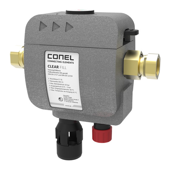
- Page 1 Montageanleitung CLEAR FILL Flasche small Installation instructions for CLEAR FILL bottle small Instrukcja montażu małej butli CLEAR FILL 1702918 • 2017/05...
- Page 2 Die beiden Hälften der Isolierschale (a) abnehmen. Beide Absperrventile (c) und (d) schließen. Durch Öffnen des Probenahmeventils (e) den Sys- temdruck ablassen. Danach das Probenahme- ventil (e) wieder schließen. Harzflasche (f) durch Linksdrehung herausschrau- ben (1) und nach unten abziehen (2). Verschlussdeckel der neuen Harzflasche ab- schrauben und damit die erschöpfte Harzflasche verschließen.
- Page 3 Den kleinen O-Ring (h) auf den Anschluss-Stutzen (i) der neuen Harzflasche (j) schieben. Den großen O-Ring (g) in die Nut der Füllstation einsetzen. O-Ringe auf korrekten Sitz prüfen! Neue Harzflasche (k) an das Außengewinde (p) der Füllstation ansetzen (1) und durch Rechtsdrehung (2) handfest anziehen.
- Page 4 Remove both halves of the insulation shell (a). Close both shut-off valves (c) and (d). Release system pressure by opening the sampling valve (e) Then reclose sampling valve (e). Unscrew (1) the resin cartridge (f) counter-clock- wise and pull down to remove (2). Use lid of new resin cartridge to close the con- sumed cartridge.
- Page 5 Slide the small O-ring (h) onto the connection noz- zle (i) of the new resin cartridge (j). Insert the large O-ring (g) into the groove of the heating circuit filling station. Ensure proper fit of O-rings! Position the new resin cartridge (q) at the external thread (p) of the heating circuit filling station (1) and tighten clockwise (2) by hand.
- Page 6 Zdjąć obie obudowy izolujące (a). Zamknąć oba zawory odcinające (c) i (d). Otwierając zawór do pobierania próbek (e), zredu- kować ciśnienie w układzie. Następnie ponownie zamknąć zawór do pobierania próbek (e). Odkręcić wkład żywiczny (f), kręcąc w lewo (1), a następnie zdjąć w dół (2). Odkręcić...
- Page 7 Wsunąć mały o-ring (h) na króciec przyłączeniowy (i) nowego wkładu żywicznego (j). Włożyć duży o-ring (g) w rowek na gwincie ze- wnętrznym stacji do napełniania. Sprawdzić o-ringi pod kątem prawidłowego osa- dzenia! Założyć nowy wkład żywiczny (k) na gwint ze- wnętrzny (p) stacji do napełniania (1) i dokręcić...
Need help?
Do you have a question about the CLEAR FILL and is the answer not in the manual?
Questions and answers