Table of Contents
Advertisement
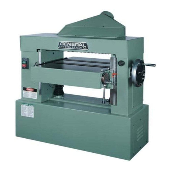
• Cast-iron breaker system. Three "v" belts drive the cutterhead.
• Large control knob of variable speed feed system to
increase or decrease speed when the planer is in operation.
• Metric and SAE graduation scale to indicate workpiece
thickness on the front of the machine.
• The anti-kickback finger system at the front of the machine
eliminates any risk of stock being forcibly ejected.
• A dust chute with its 6" outlet to receive a dust collector.
• Magnetic control with overload protection.
FEATURES
TABLE SIZES
MAXIMUM PLANING WIDTH
MAXIMUM PLANING THICKNESS
MINIMUM PLANING THICKNESS
MINIMUM PLANING LENGTH
MAXIMUM PLANING DEPTH
CUTTERHEAD DIAMETER
KNIVES
CUTTERHEAD SPEED
FEEDING SPEED (VARIABLE)
CUTS PER INCHE (25.4 mm)
MOTOR
WEIGHT
MODEL 30-460 / 30-460HC
⁄
1
25
" x 28" (660 x 711 mm)
4
24" (610 mm)
8" (203 mm)
⁄
3
" (4.75 mm)
16
8" (203 mm)
⁄
5
" (8 mm)
16
⁄
⁄
1
5
/
3
" (80 mm)
3
" (84 mm)
8
16
/
3
HELICAL
4800 RPM
20 TO 38 FPM (6 TO 11.6 M/MIN)
62.5/20 FPM TO 33/38 FPM
M2
10 HP, 220 V, 3 Ph
10 HP, 600 V, 3 Ph
M3
1015 LBS (460 kg)
/
---
Advertisement
Table of Contents

Related Manuals for General International 30-460


Summary of Contents for General International 30-460
- Page 1 SPECIFICATIONS ˇ FEATURES MODEL 30-460 / 30-460HC • Cast-iron breaker system. Three “v” belts drive the cutterhead. ⁄ TABLE SIZES ” x 28” (660 x 711 mm) • Large control knob of variable speed feed system to increase or decrease speed when the planer is in operation.
- Page 2 GENERAL ® INTERNATIONAL guarantee All component parts of GENERAL INTERNATIONAL machinery are carefully inspected during all production stages and each machine is thoroughly inspected upon completion of assembly. Because of quality, GENERAL INTERNATIONAL agrees to repair or replace any genuine part or parts which, upon examination, proves to be defective in workmanship or material within a period of 24 months from date of purchase.In order to obtain warrantee, all defective parts must be returned...
- Page 3 UNPACKING AND CLEANUP To ensure maximum performance from your GENERAL® INTERNATIONAL 24» industrial planer 30-460, clean it properly; and install it accurately before use. As soon as you receive the planer, we recommend you follow these procedures: The 24»...
- Page 4 INSTALLATION FIG. 3 Remove the fastening bolts from the machine to the shipping skid. Two lifting lugs are built into the machine, one of which is illus- trated in (Fig.3,A). These lugs can be used to mechanically lift the machine using a forklift and lifting straps.
- Page 5 ASSEMBLING DUST HOOD A dust hood with a 5» opening is supplied with your machine and is to be used when connecting the planer to a dust collector or a central dust collection system. Position dust hood (A) Fig.8, against the rear of the machine and on the top of cutterhead guard (B). Align the holes and fasten the dust hood (A) Fig.9, to the cutterhead guard (B) using eight 6mm-button head screws (C) as illustrated in Fig.9.
- Page 6 CHANGING VOLTAGE If you must reconnect your machine for 220 or 440-volt operation, please contact or have a certified electrician connect the machine to the power source. FIG. 13 GROUNDING Machine must be properly grounded in order to avoid electric shock to the work operator.
- Page 7 TABLE ROLLS (Fig.17) FIG. 17 The planer is equipped with two-table rolls (A); which aid in feeding the stock. This will reduce friction between the stock and the table and will rotate as the stock is fed through the planer. To raise the table rolls, loosen lock lever (B) as illustrated in Fig.17 and pull control lever (C) upwards to the required height setting.
- Page 8 If an adjustment to the outfeed table roll is necessary loosen lock- FIG. 22 nut (G) Fig.22, located under the table below the outfeed table roll (F). Rotate the adjustment nuts (H) as required; in order to raise or lower the height of the outfeed roll (F). NOTE: it will be necessary to raise the table in order to gain access to the adjustment nuts.
- Page 9 If an adjustment to one or all three knives is necessary, slightly FIG. 26 loosen the 12 locking screws, 10 of which are shown in Fig.26 & Fig.27 (F) loosen just enough to relieve stress in the cutterhead (B) and do not disturb the knife setting. With the knife setting gauge (C) Fig.26 &...
- Page 10 ADJUSTING CHIPBREAKERS FIG. 29 The chipbreakers (A) Fig.29, are located on the top of the planer and extend downward around the front of the cutterhead. The chipbreakers will raise as stock is fed through the planer and «breaks or cuds» the wood chips.
- Page 11 FIG. 33 FIG. 34 ADJUSTING OUTFEED ROLL FIG. 35 The outfeed roll continues to feed the stock out of the machine after the planing operation is completed and should be set at .030» below the cutting circle. To check and adjust the setting of the outfeed roll, proceed with the following: Disconnect the machine from the power source.
- Page 12 Place the gauge block (A) Fig.38 on the table, directly under the FIG. 38 cutterhead (B). Use a .040» feeler gauge (C) and place on top the gauge block (A), raise the table until the cutterhead knife slightly touches the feeler gauge (A) when the knife is at its lowest point.
- Page 13 ADJUSTING TABLE HEIGHT SCALE FIG. 43 The table height scale indicates the distance the table is from the cutting circle (depth of cut). To verify and adjust the pointer, proceed with the following steps: Run a piece of wood through the planer and stop the machine. Measure the thickness of the planed end of the stock as illustrated in Fig.44.
- Page 14 PARTS LIST 30-460 PART N0. REFERENCE NO. DESCRIPTION SPECIFICATION 30460-A01 C003016 (L) COLUMN BASE 30460-A02 C003017 (R) COLUMN BASE G002008 30460-A03 ELEVATING SCREW 30460-A04 S284008 SPRING WASHER 10.2 x 18.8 x 3.9 x 3.0T S137005 M10-P1.5 x 30L 30460-A05 SCREW...
- Page 15 PARTS LIST 30-460 PART N0. REFERENCE NO. DESCRIPTION SPECIFICATION 30460-B01 G003013 WORK TABLE 30460-B02 C007001 TABLE GUIDE T013027 30460-B03 ROLLER 30460-B04 C020003 GUIDE C051019 30460-B05 COLLOR S284014 30460-B06 SPRING WASHER 30460-B07 S136007 SCREW S136003 30460-B08 SCREW 30460-B09 S213006 SCREW 30460-B10...
- Page 16 PARTS LIST 30-460 PART N0. REFERENCE NO. DESCRIPTION SPECIFICATION 30460-C01 T001034 CUTTERHEAD ASS’Y 30460-C02 S284008 SPRING WASHER 10.2 x 18.4 x 3.7 x 2.5T S203006 M10-P1.5 x 30L 30460-C03 SCREW 30460-C04 C015029 BRACKET (L) C015096 30460-C05 BRACKET (R) C046073 19.05 x 678L...
- Page 17 PARTS LIST 30-460 PART N0. REFERENCE NO. DESCRIPTION SPECIFICATION 30460-D01 G006011 GEAR BOX ASS’Y 30460-D02 S282011 WASHER 10.5 x 25 x 2T S284008 10.2 x 18.4 x 3.7 x 2.5T 30460-D03 SPRING WASHER 30460-D04 S137005 SCREW M10-P1.5 x 30L T017006 30460-D05 LINK ASS’Y...
- Page 18 PARTS LIST 30-460 PART N0. REFERENCE NO. DESCRIPTION SPECIFICATION 30460-E01 T020038 BASE 30460-E02 C073079 TOP COVER C061001 30460-E03 TOP COVER BRACKET 30460-E04 S284014 SPRING WASHER 8.5 x 15.6 x 3.2 x 2.5T S136005 M8-P1.25 x 30 L 30460-E05 SCREW C061002...
- Page 19 PARTS LIST 30-460 PART N0. REFERENCE NO. DESCRIPTION SPECIFICATION 30460-F01 C015094 PLATE 30460-F02 T016008 LEVEL GEAR S284014 8.5 x 15.6 x 3.3 x 2.5T 30460-F03 SPRING WASHER 30460-F04 S202006 SCREW Ü T003003 30460-F05 LEVEL SCREW...
- Page 20 PARTS LIST 30-460 PART N0. REFERENCE NO. DESCRIPTION SPECIFICATION 30460-G01 T012029 TABLE WHEEL 30460-G02 C017014 C057006 30460-G03 LEVER 30460-G04 S273043 M12-P1.75 S282011 10.5 x 25 x 2.0T 30460-G05 WASHER P028001 30460-G06 LOCK LEVER 30460-G07 S214006 SET SCREW M10-P1.5 x 30L S273042 M10-P1.5...
- Page 21 PARTS LIST 30-460 PART N0. REFERENCE NO. DESCRIPTION SPECIFICATION 30460-H01 T014002 REDUCER GEAR BOX ASS’Y 30460-H02 T015008 GEAR PULLEY ASS’Y S284007 8.2 x 15.4 x 3.2 x 2.0T 30460-H03 SPRING WASHER 30460-H04 S136004 SCREW M8-P1.25 X25l...
- Page 22 PARTS LIST 30-460 PART N0. REFERENCE NO. DESCRIPTION SPECIFICATION 30460-I01 C011023 CUTTERHEAD 30460-I02 C009054 (R) SUPPORT S026048 6008ZZ, 40 x 68 x 15 30460-I03 BEARING 30460-I04 C009053 (L) SUPPORT C010026 30460-I05 (R) SUPPORT S284006 6.1 x 12.2 x 2.7 x 1.5T...
- Page 23 PARTS LIST 30-460 PART N0. REFERENCE NO. DESCRIPTION SPECIFICATION 30460-J01 C009021 SUPPORT 30460-J02 P051001 BEARING 19.05 x 22.2 x 25 x 18L S043005 (2904) 20 x 35 x 10 30460-J03 THRUST BEARING 30460-J04 C035001 SHAFT C028001 30460-J05 GEAR S267168 5 x 40L...
- Page 24 PARTS LIST 30-460 PART N0. REFERENCE NO. DESCRIPTION SPECIFICATION 30460-K01 P041008 MOTOR 3HP 1PH 30460-K02 C064125 MOTOR PULLEY S214006 M10-P1.5 x 30L 30460-K03 SET SCREW 30460-K04 C063003 MOTOR BRACKET S282011 10.5 x 25 x 2T 30460-K05 WASHER S284008 10.2 x 18.4 x 3.7 x 2.5T...
- Page 25 PARTS LIST 30-460 PART N0. REFERENCE NO. DESCRIPTION SPECIFICATION 30460-L01 C009067 HOUSING 30460-L02 S026042 BEARING 6006ZZ 30 x 62 x 16 S026123 6205ZZ 25 x 52 x 15 30460-L03 BEARING 30460-L04 S298080 RETAINING RING 52 x 2.2 C047078 30460-L05 PULLEY SHAFT S298015 25 x 1.35...
- Page 26 PARTS LIST 30-460 PART N0. REFERENCE NO. DESCRIPTION SPECIFICATION 30460-M01 C042009 CHIP BREAKER 30460-M02 C060008 SPRING S282010 8.4 x 15.5 x 1.6T 30460-M03 SPRING WASHER 30460-M04 S136004 SCREW M8-p1.25 x 25L C048037 30460-M05 SHAFT C015095 30460-M06 SUPPORT (L) 30460-M07 S284009 SPRING 12.2 x 21.5 x 4.2 x 3.0T...
- Page 27 PARTS LIST 30-460 PART N0. REFERENCE NO. DESCRIPTION SPECIFICATION 30460-N01 C046073 FINGER ROD 19.05 x 678L 30460-N02 C052077 FINGER C045012 30460-N03 COLLAR 30460-N04 C052014 BUSHING...
- Page 28 PARTS LIST 30-460 PART N0. REFERENCE NO. DESCRIPTION SPECIFICATION 30460-O01 C039027 INFEED SHAFT 30460-O02 C038006 INFEED ROLL S318021 30460-O03 RUBBER BUSHING 30460-O04 C051023 BUSHING S213001 M8-P1.25 x 12L 30460-O05 SET SCREW C009017 30460-O06 BEARING BLOCK (R) 30460-O07 C009049 BEARING BLOCK (L)
- Page 29 PARTS LIST 30-460 PART N0. REFERENCE NO. DESCRIPTION SPECIFICATION 30460-P01 C039028 OUTFEED ROLLER 30460-P02 C009017 BEARING C009049 30460-P03 BEARING 30460-P04 P051002 BEARING 30 x 36 x 38L C067015 30460-P05 SPROCKET S003073 6 x 6 x 25L 30460-P06 30460-P07 S282049 WASHER...
- Page 30 PARTS LIST 30-460 PART N0. REFERENCE NO. DESCRIPTION SPECIFICATION 30460-Q01 C006054 TABLE M6-P1.0 x 16L 30460-Q02 C015018 SUPPORT S201004 30460-Q03 SCREW 30460-Q04 C017013 C046076 5 x 40L 30460-Q05 SPRING PIN S267168 30460-Q06 30460-Q07 C051008 BUSHING S213015 M8-P1.25 x 8L 30460-Q08...
- Page 31 PARTS LIST 30-460 PART N0. REFERENCE NO. DESCRIPTION SPECIFICATION 30460-R01 C040039 ROLLER 30460-R02 C009008 SUPPORT S026132 6205ZZ 25 x 52 x 15 30460-R03 BEARING 30460-R04 S298080 C-RING 52 x 2.2 C051020 30460-R05 COLLAR S273042 M10-P1.5 30460-R06 Ü 30460-R07 S137020 SCREW...
- Page 32 PARTS LIST 30-460 PART N0. REFERENCE NO. DESCRIPTION SPECIFICATION 30460-S01 C029003 GEAR 30460-S02 C039003 GEAR SHAFT S137003 M10-P1.5 X20L 30460-S03 SCREW 10x206cm 30460-S04 S026135 BALL BEARING 6206ZZ 30x62x16 C031001 30460-S05 GEAR HOUSING S026126 6203ZZ 17x40x12 30460-S06 BALL BEARING 30460-S07 C009022...
- Page 33 PARTS LIST 30-460 PART N0. REFERENCE NO. DESCRIPTION SPECIFICATION 30460-T01 C009005 HOUSING 30460-T02 S026129 BALL BEARING 6204ZZ 20 x 47 x 14 S026132 6205ZZ 25 x 52 x 15 30460-T03 BALL BEARING 30460-T04 C0029007 PINION GEAR C064017 30460-T05 PULLEY C064016...
- Page 34 PARTS LIST 30-460 PART N0. REFERENCE NO. DESCRIPTION SPECIFICATION 30460-U01 C015015 SUPPORT 30460-U02 P051001 BEARING 19.05 x 22.2 C039026 19.05 x 662L 30460-U03 SHAFT 30460-U04 C028002 GEAR S267166 5 x 30L 30460-U05 C067018 30460-U06 SPROCKET...
- Page 35 PARTS LIST 30-460 PART N0. REFERENCE NO. DESCRIPTION SPECIFICATION 30460-V01 C066004 WHEEL 30460-V02 P051001 BEARING 19.05 x 22.2 x 25 x 18L C052016 30460-V03 BUSHING 30460-V04 S137005 SCREW M10-P1.5 x 30L C049018 30460-V05 LINK C015030 30460-V06 LINK SUPPORT 30460-V07 C051024...
- Page 36 PARTS LIST 30-460 PART N0. REFERENCE NO. DESCRIPTION SPECIFICATION 30460-W01 C085001 SWITCH BOX 30460-W02 S284020 SPRING WASHER 4.1 x 7 x 1.7 x 1.0T S224101 5/32» - 32NC x 6L 30460-W03 RD HD SCREW 30460-W04 S3114011 SWITCH S273100 5/32» - 32NC...
- Page 37 NOTES...
- Page 38 30-460 8360, Champ-d’Eau, Montreal (Quebec) Canada H1P 1Y3 Tel.: (514) 326-1161 Fax : (514) 326-5555 www.general.ca IMPORTANT: When ordering replacement parts, always give the model number, serial number of the machine and part number. Also a brief description of each item and quantity desired.
Need help?
Do you have a question about the 30-460 and is the answer not in the manual?
Questions and answers