Table of Contents
Advertisement
FEATURES
Powerful 2 HP 15 A motor with thermal
overload protection.
Front and rear fold-down extension tables
for smooth easy stock feeding.
Top mounted rollers for multiple passes.
Built-in inset lifting handles.
Large depth of cut adjustment handle –
one full rotation equals 1/16".
Easy to read thickness indicator with
graduated scale in inches and metric.
Safety on/off switch with key. Unit cannot
be started when key is removed from
switch.
Depth of cut indicator.
Helical cutter head with 26 reversible two-
sided high speed steel inserts.
SPECIFICATIONS
TABLE AREA WITH EXTENSIONS (L X W)
28 3⁄8" X 13" (720 X 330 MM)
MAXIMUM PLANING WIDTH
13" (330 MM)
MAXIMUM THICKNESS OF STOCK
6" (152 mm)
MINIMUM THICKNESS OF STOCK
1⁄8" (3 mm)
MINIMUM LENGTH OF STOCK
5" (127 MM)
MAXIMUM DEPTH OF CUT (FULL WIDTH)
1⁄16" (1.5 MM)
CUTTER HEAD SPEED
9700 RPM
FEED SPEED
26 FPM
MOTOR
2 HP , 120 V, 1 PH, 15 A
WEIGHT
59 LBS (27 KG)
REVISION 1 - AUGUST 26 /10
© Copyright General® International 08/2010
Advertisement
Table of Contents

Related Manuals for General International 30-005HC-M1


Summary of Contents for General International 30-005HC-M1
-
Page 1: Specifications
FEATURES Powerful 2 HP 15 A motor with thermal overload protection. Front and rear fold-down extension tables for smooth easy stock feeding. Top mounted rollers for multiple passes. Built-in inset lifting handles. Large depth of cut adjustment handle – one full rotation equals 1/16”. Easy to read thickness indicator with graduated scale in inches and metric. - Page 2 GENERAL® INTERNATIONAL 8360 Champ-d’Eau, Montreal (Quebec) Canada H1P 1Y3 Telephone (514) 326-1161 • Fax (514) 326-5555 • www.general.ca THANK YOU for choosing this General ® International model 30-005HC M1 13” Planer with Helical Cutter Head. This planer has been carefully tested and inspected before shipment and if properly used and maintained, will provide you with years of reliable service.
- Page 3 ® ® GENERAL & GENERAL INTERNATIONAL WARRANTY All component parts of General®, General® International and Excalibur by General International ® products are carefully inspected during all stages of production and each unit is thoroughly inspected upon completion of assembly. Limited Lifetime Warranty Because of our commitment to quality and customer satisfaction, General®...
-
Page 4: Table Of Contents
TABLE OF CONTENTS Rules for safe operation Operating Instructions ....5 ... Basic principles of planing ......12 Electrical requirements . -
Page 5: Rules For Safe Operation
RULES FOR SAFE OPERATION To help ensure safe operation, please take a moment to learn the machine’s applications and limitations, as well as poten- tial hazards. General® International disclaims any real or implied warranty and holds itself harmless for any injury that may result from improper use of its equipment. -
Page 6: Electrical Requirements
ELECTRICAL REQUIREMENTS BEFORE CONNECTING THE MACHINE TO THE POWER SOURCE, VERIFY THAT THE VOLTAGE OF YOUR POWER SUPPLY CORRESPONDS WITH THE VOLTAGE SPECIFIED ON THE MOTOR I.D. NAMEPLATE. A POWER SOURCE WITH GREATER VOLTAGE THAN NEEDED CAN RESULT IN SERIOUS INJURY TO THE USER AS WELL AS DAMAGE TO THE MACHINE. IF IN DOUBT, CONTACT A QUALIFIED ELECTRICIAN BEFORE CONNECTING TO THE POWER SOURCE. -
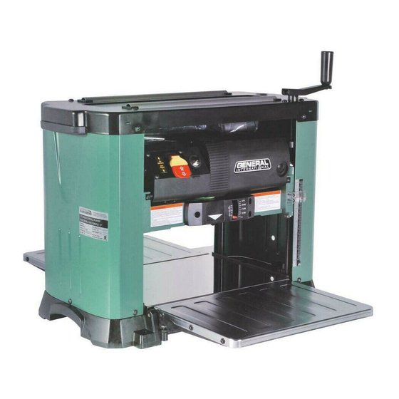
Page 7: Identification Of Main Parts And Components
13” PLANER WITH HELICAL CUTTER HEAD 30-005HC M1 IDENTIFICATION OF MAIN PARTS AND COMPONENTS REAR VIEW IN-FEED TABLE DEPTH OF CUT INDICATOR STOCK THICKNESS SCALE OUT-FEED TABLE HEIGHT ADJUSTMENT HANDLE TOOL STORAGE RETURN ROLLERS DUST CHUTE CIRCUIT BREAKER ON/OFF SWITCH W/SAFETY KEY... -
Page 8: Unpacking
NOTE: Please report any damaged or missing items to your General International distributor immediately. LIST OF CONTENTS A- PLANER................1 ADJUSTMENT HANDLE ...........1 C- DUST CHUTE ..............1... -
Page 9: Attach The Depth Of Cut Adjustment Handle
If a permanent shop placement or installation is prac- If you prefer an optional steel stand (item #30-006) tical, consider using the mounting holes and drilling is available from your local General International matching through holes in your workbench or mount- dealer. -
Page 10: On/Off Power Switch
ON/OFF POWER SWITCH SAFETY KEY POWER ON POWER OFF (PREVENTS START-UP WHEN REMOVED) This planer is equipped with a rocker style ON/OFF switch located on the front left hand side of the cutter head. To start the planer, insert the lock-out key as shown in A and pull up on the lower portion of the switch as shown, B. To stop the planer, push down on the switch, C. -
Page 11: Depth Of Cut Indicator
DEPTH OF CUT INDICATOR The depth of cut indicator, A, will indicate how much material the cutterhead is set to remove from the work- piece for a given pass. The pointer will read zero until the workpiece engages the front of the cutterhead. Place the workpiece under the front of the cutterhead and turn the height adjustment handle clockwise until the cutterhead makes contact with the workpiece &... -
Page 12: Rated Limits Of This Planer
RATED LIMITS OF THIS PLANER THE MAXIMUM PLANING WIDTH OF THIS UNIT IS 13”. THE MAXIMUM WORKPIECE THICKNESS OF THIS UNIT IS 6” THE MINIMUM THICKNESS TO WHICH A WORKPIECE CAN BE SAFELY PLANED WITH THIS UNIT IS 1/8” . THE MINIMUM WORKPIECE LENGTH THAT CAN BE SAFELY PLANED WITH THIS UNIT IS 5”. -
Page 13: Planing Step-By-Step
PLANING STEP-BY-STEP 1. With the planer turned off, position the workpiece 2. If a specific pre-set thickness is required, set the on the infeed table with the flat face down and the depth stop to the desired final workpiece thickness. face to be planed facing up. -
Page 14: Maintenance & Adjustments
Step to the rear of the machine and recover the 10. The return rollers on the top of the planer can be planed board on the outfeed table once it has used to pass the workpiece back to the front of cleared the outfeed roller and has stopped the machine for repeat passes. -
Page 15: Inspecting/Replacing Cutterhead Knives
To maintain even insert wear always reverse all 26 inserts each time knife replacement is required. If one of the inserts has been nicked or damaged on one of it’s edges, it can be simply reversed instead of replaced. When needed, replacement inserts B can be ordered through your local General International distributor under item #30-007. - Page 16 1. Turn off and unplug the machine from the power 3. Using the supplied allen key, loosen and remove source. the 4 button head screws A, and remove the dust chute. 2. Set the pre-set depth gauge to 3/4” so that the stop pin prevents the cutter head from going any lower.
-
Page 17: Replacing The V-Belt
REPLACING THE V-BELT The cutter head is driven by a flat ribbed belt that is located on the right-hand side of the planer facing the infeed side. MAKE SURE THE PLANER HAS BEEN TURNED OFF AND UNPLUGGED FROM THE POWER SOURCE BEFORE PERFORMING ANY MAINTENANCE. -
Page 18: Recommended Optional Accessories
RECOMMENDED OPTIONAL ACCESSORIES We offer a large variety of products for increased convenience, productivity, accuracy and safety when using your planer. Here’s a small sampling of optional accessories available from your local General International dealer. For more information about our products, please visit our website at www.general.ca... - Page 19 FRAME ASSEMBLY 12(2) 13(4) 8(15) 10(3) 17(4) 14(2) 55(4) 17-1(4) 28(4) 27(3) 31(4) 32(4) 33(4) 34(5) 35(4) 46(12) 36(10) 37(4) 38(4) 42(2) 39(4) 43(2) 40(4) 44(2) 47(4) 48(4) 49(4) 50(4) 51(2)
- Page 20 MAIN ASSEMBLY...
- Page 21 PARTS LIST 30-005HC M1 PART N0. REF. N0. DESCRIPTION SPECIFICATION 30005-01 HANDLE ASSEMBLY 30005-02 CAP SCREW M5xP0.8x20L 30005-08 BUTTON HEAD SCREW M6xP1.0x8L 30005-09 TOP COVER 30005-10 SHAFT BUSHING 30005-11 UPPER BEARING SEAT 30005-12 RETURN ROLLER 30005-13 ROLLER SEAT 30005-14 LIFTING HANDLE 30005-15 SPACER 30005-16...
- Page 22 PARTS LIST 30-005HC M1 PART N0.REF. N0. DESCRIPTION SPECIFICATION 30005-61 CUTTER HEAD BEARING SEAT 30005-62 CUTTER HEAD BEARING 6203ZZ 30005-63 BEARING RETAINER 30005-64 PHILLIPS HEAD SCREW M3xP0.5X8L 30005-65 5x5x12mm 30005-66 HELICAL CUTTER HEAD 30005-67 CUTTER HEAD INSERTS (see #30-007 - set of 10 inserts) 14x14x2mmt 30005-68 TORX SCREW (see #30-008)
- Page 23 PARTS LIST 30-005HC M1 PART N0. REF. N0. DESCRIPTION SPECIFICATION 30005-161 MOTOR FAN COVER 30005-162 WAVE WASHER 30005-163 BEARING 6201 LLB 30005-164 ARMATURE 30005-165 SLEEVE 30005-166 POWER CORD CLAMP GCL5/16S 30005-167 STATOR 120V/60Hz 30005-168 PHILLIPS HEAD SCREW M4.8x75L 30005-169 MOTOR HOUSING 30005-170 SET SCREW M5xP0.8x8mmL...
- Page 24 MODEL 30-005HC M1 8360 Champ-d’Eau, Montreal (Quebec) Canada H1P 1Y3 Tel.: (514) 326-1161 Fax: (514) 326-5565 - Fax: (514) 326-5555 - Parts & Service / Order Desk orderdesk@general.ca www.general.ca IMPORTANT When ordering replacement parts, always give the model number, serial number of the machine and part number.
Need help?
Do you have a question about the 30-005HC-M1 and is the answer not in the manual?
Questions and answers
Can I adjust the feed roll hight