Table of Contents
Advertisement
Quick Links
Conforms To EC Directives
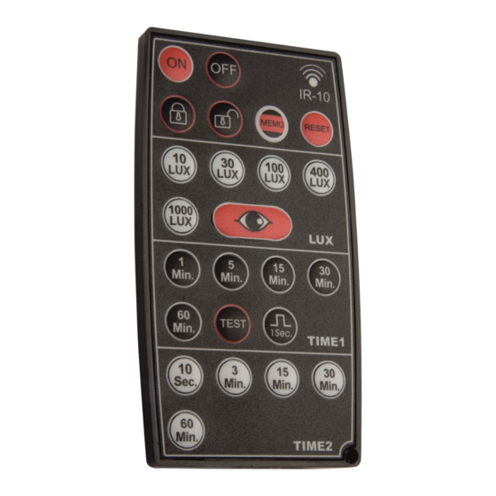
IR Remote Control IR-10 Instructions
Technical Specifications
Rated Voltage:
3V DC (CR2032 battery)
Transmission Range:
Min. 4m (IR-10 directly below detector)
Transmission Angle:
35º (above range is reduced to approx.
3m at extremes of transmission angle)
Operating Temperature:
0ºC to +45ºC
Storage Temperature:
-25ºC to +55ºC
1
Package Contents
Visual I.D.
Item
Remote Control
Quantity
2
Features
2.1 No need for climbing up ladders, the ceiling mounted presence
detector can be adjusted and set up easily by a user with an IR-10.
2.2 By pressing "
" button the actual light level can be read-in to
the sensor. (Refer to function of "
2.3 The IR-10 can be attached to a
key ring chain for convenience.
(See Fig.1)
2.4 To render the IR-10 operational
remove the battery isolating
strip by pulling the exposed
tab away from the IR-10 body.
3
Battery Replacement
Lever out the battery holder with a screwdriver, then replace the battery
(type CR2032 3V). Please make sure the battery is the right way up,
then push the battery holder back. (See Fig.2)
Fig. 2
Model IR-10
Conforms To EC Directives
IR Remote Control IR-10 Instructions
4
Push Button Function
Note
• Adjustments can only be made in Unlocked Mode.
• By use of the
button the operational settings mode for one unit
can be loaded into other units in the same area.
It also allows return to previous operational settings after a Reset.
• The maximum IR transmit time when a button is pressed is 1 second,
pressing a button for longer than this is not effective.
• Pressing more than one button simultaneously will result in a failed
Model IR-10
transmission.
• Commands and operational settings are all confirmed by around
Technical Specifications
2 seconds of rapid flashing of the sensor LED except for
(see relevant section).
Rated Voltage:
3V DC (CR2032 battery)
Transmission Range:
Approx. 3M
• Time setting for load II (HVAC) is only available with PDSM362 and
PDFM362.
Transmission Angle:
35º
Operating Temperature:
0ºC to +45ºC
Storage Temperature:
-25ºC to +55ºC
Push
Function
Button
1
Sensor load I ON
Package Contents
• By pressing the "
" button load I will be switched
Instructions
1
1
" button).
Fig. 1
Key Chain
Hole
4
Push Button Function
• Adjustments can only be made in Unlocked Mode.
• The sensor may be set to continuously ON or OFF for 8 hours as well
as detection mode controlled by or independent of light level.
• By use of the
button the operational settings made for one unit
can be loaded into other units in the same area.
It also allows return to previous operational settings after a Reset.
• The maximum IR transmit time when a button is pressed is 1 second,
pressing a button for longer than this is not effective (except
• Pressing more than one button simultaneously will result in a failed
transmission.
• Commands and operational settings are all confirmed by around
2 seconds of rapid flashing of the sensor LED except for
(see relevant section).
• Time setting for load II (HVAC) is only available with PDSM362 and
PDFM362.
Push
Button
Sensor load I ON
• By pressing the "
on for 8hrs, this is confirmed by around 2sec rapid
(Command)
flashing of the sensor LED. The sensor LED flashes 1sec
ON and 5sec OFF during the ON mode. No movement
can be detected by the sensor during the ON mode.
• Exit the ON mode and return to Auto mode either by
pressing the "
rapid flashing of the sensor LED) or by re-supplying
power after it has been turned off for at least 10 seconds.
• Load I can be switched to the OFF mode by pressing
the "
" button during an ON period (confirmed by
around 2sec rapid flashing of the sensor LED).
Sensor load I OFF
• By pressing the "
off for 8hrs, (confirmed by around 2sec rapid flashing
(Command)
of the sensor LED). The sensor LED flashes 1sec ON and
5sec OFF during the OFF mode. No movement can be
detected by the sensor during the OFF mode.
• Exit the OFF mode and return to Auto mode either by
pressing "
" or to re-supply power after it has been
turned off for at least 10sec.
• Load I can be switched to the ON mode by pressing
the "
" button during an OFF period (confirmed by
around 2sec rapid flashing of the sensor LED).
Locking of IR-10
• By pressing the "
and no button will function except "
(Command)
by around 2sec rapid flashing of the sensor LED.
Unlocking of IR-10
• By pressing the "
(all buttons will now function). This is confirmed by
(Command)
around 2 sec rapid flashing of the sensor LED.
Note
Function
" button load I will be switched
" button (confirmed by around 2sec
" button load I will be switched
" button the IR-10 can be locked
". It is confirmed
" button the IR-10 is unlocked,
).
Advertisement
Table of Contents

Related Manuals for Timeguard IR-10


Summary of Contents for Timeguard IR-10
- Page 1 • Load I can be switched to the OFF mode by pressing 2.1 No need for climbing up ladders, the ceiling mounted presence detector can be adjusted and set up easily by a user with an IR-10. the “ “ button during an ON period (confirmed by around 2sec rapid flashing of the sensor LED).
- Page 2 Push Function Trouble Shooting Button If the IR-10 remote control does not work follow the flow chart in 5.1. Lux value adjustment for load I • The operating light threshold, below which the unit 5.1 Trouble shooting for IR-10 only...
Need help?
Do you have a question about the IR-10 and is the answer not in the manual?
Questions and answers