Table of Contents
Advertisement
Quick Links
Advertisement
Table of Contents

Related Manuals for Minebea OPT-563B-71

Summary of Contents for Minebea OPT-563B-71
- Page 1 DIGITAL TRANSMITTER CANopen Interface OPT-563B-71 Instruction Manual EN294-1634C...
-
Page 3: Pictograms And Conventions Used In This Manual
Introduction Thank you for your purchasing OPT-563B-71 Digital Transmitter with CANopen interface for optical transmission system flange torque converters. This instruction manual describes how to operate the device and discusses noteworthy points. Note that handling or operating the device incorrectly may result in malfunctions. Read this manual thoroughly before use for correct usage. -
Page 4: About This Manual
About This Manual This instruction manual describes the connection and usage procedures for CANopen interface specifications available separately for the OPT-563B. For details of other functions, basic handling instructions, and precautions concerning the OPT-563B, refer to the OPT-563B Instruction Manual. ... -
Page 5: Revision History
Due to ECN No, FN16-02057 -Deletion- 2016/06 DRW. NO. EN294-1634A Delete 'Minebea Co., Ltd. Measuring Components Business Unit' from the front cover. Due to ECN No, FN16-02139 ROM Ver1.800 or later 5-1. Sub Index of Index "0x2001" and "0x2002" is changed to 2016/09 DRW. -
Page 6: Table Of Contents
Contents Introduction ................................I Pictograms and Conventions Used in This Manual .................... I About This Manual ..............................II Revision History ..............................III Overview................................1 1-1. Features................................ 1 Part Names and Functions ..........................2 2-1. Rear Panel CANopen Interface ........................2 Connections .............................. -
Page 7: Overview
It supports CANopen communication functions (CiA DS301) by adding a CANopen interface to the OPT-563B. 1-1. Features The main features of the OPT-563B-71 are as follows: (1) PDO transfer Supports PDO transmission. Receiving is not supported. Torque + rotation speed ... -
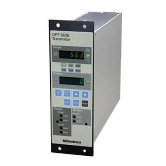
Page 8: Part Names And Functions
2. Part Names and Functions 2-1. Rear Panel CANopen Interface (2) Status LEDs (1) Interface connector (1) Interface connector Connector for the CANopen interface The connector pins are configured as follows: Pin No. Signal name Details N.C. Not used CAN_L CAN signal Low CAN_GND CAN ground... -
Page 9: Connections
ERR LED (red) State Description Off or operating Blinks once Error counter reached or exceeded preset value Flickering Automatically detecting baud rate NMT slave or NMT master detected a Heartbeat event Blinks twice (Heartbeat consumer) Bus off 3. Connections 3-1. Interface Connector Pin Arrangement Refer to "2-1. -
Page 10: Canopen Communication Settings
The settings take effect after power is turned off, then turned back on. Turn power off and then back on after changing any of the settings An EDS file must be loaded when setting CANopen objects. If necessary, this can be downloaded from the our website (http://www.minebea-mcd.com/) -
Page 11: Access Sequences
5. Access Sequences CANopen is accessed as shown in the following diagrams. (1) PDO transmission ① Timer event OPT-563B System Software CANopen Rotation speed Torque interface ② Information sensor converter Master acquisition ④ PDO ③ DPRAM device trans- Torque sensor update mission CANbus... -
Page 12: Canopen Object Mapping
5-2. CANopen Object Mapping Manufacturer-specific Object Index Sub-index Order# Data Type Data (ADI# + 0x2000) (ADI Element#) 0x2001 0x00 SINT32 Torque (*1) 0x2002 0x00 SINT32 Rotation speed (*2) 0x01 UINT32 Torque status (*3) 0x2011 0x02 UINT32 Rotation speed status (*4) 0x2333 0x00 UINT16... - Page 13 (*3) Torque status format (UINT32) d.c. d.c. d.c. d.c. IN-1 bit0(ST): 1: Torque value normal 0: Error value bit1(+OL): 1: +OL error, 0: Normal bit2(-OL): 1: -OL error, 0: Normal bit3(IN-1): 1: IN-1 error, 0: Normal bit16(EPR): 1: EEPROM error, 0: Normal bit17(CER): 1: PDO communication error, 0: Normal (*4) Rotation speed status format (UINT32)
- Page 14 SDO Mapping Details CANopen Object Writing Remarks Manufacturer device name 0x1008 - 0x00 Manufacturer hardware version 0x1009 - 0x00 Manufacturer software version 0x100A - 0x00 See "Manufacturer-specific Torque, rotation speed, status Object." Torque units, decimal places, See "Manufacturer-specific polarity Object." Rotation speed units, decimal See "Manufacturer-specific places...
-
Page 15: Errors
6. Errors Error Details IN-1 error Displayed when no torque signal is input in measurement mode or monitor mode Displayed when the input torque exceeds [+110% of maximum display value] or 16 +OL error kHz in measurement mode Displayed when the input torque is less than [-110% of maximum display value] or -OL error 4 kHz in measurement mode +OS error... -
Page 16: Interface Specifications
7. Interface Specifications 7-1. CANopen Interface Specifications Specifications Details Baud rate Select from 10 kbps, 20 kbps, 50 kbps, 100 kbps, 125 kbps, 250 kbps, 500 kbps, 800 kbps, and 1 Mbps. Node ID Select a value from 001 to 127. PDO output interval Select a value from 000 to 100 (Units: ms). - Page 18 1-1-1, Katase, Fujisawa-shi, Kanagawa-ken, 251-8531 Japan Tel: +81-466-23-2681 Fax: +81-466-22-7191 Sensing Device Business Unit FUJISAWA PLANT 1-1-1, Katase, Fujisawa-shi, Kanagawa-ken, 251-8531 Japan Tel: +81-466-22-7151 Fax: +81-466-22-1701 KARUIZAWA PLANT 4106-73 Miyota, Miyota-machi, Kitasaku gun, Nagano-ken 389-0293 Japan Tel: +81-267-31-1309 Fax: +81-267-31-1353 HOMEPAGE ADDRESS http://www.minebea-mcd.com...
Need help?
Do you have a question about the OPT-563B-71 and is the answer not in the manual?
Questions and answers