Table of Contents
Advertisement
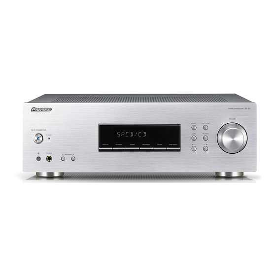
STEREO RECEIVER
SX-20-K
SX-20-S
THIS MANUAL IS APPLICABLE TO THE FOLLOWING MODEL(S) AND TYPE(S).
Model
Type
SX-20-K
YXE8
SX-20-S
YXE8
PIONEER CORPORATION
PIONEER ELECTRONICS (USA) INC. P.O. Box 1760, Long Beach, CA 90801-1760, U.S.A.
PIONEER EUROPE NV Haven 1087, Keetberglaan 1, 9120 Melsele, Belgium
PIONEER ELECTRONICS ASIACENTRE PTE. LTD. 253 Alexandra Road, #04-01, Singapore 159936
PIONEER CORPORATION
STANDBY
ON
STANDBY
PHONES
Power Requirement
AC 220 V to 230 V
AC 220 V to 230 V
1-1, Shin-ogura, Saiwai-ku, Kawasaki-shi, Kanagawa 212-0031, Japan
2012
STEREO RECEIVER
VOLUME
MEMORY
TUNE / PRESET
TONE
BALANCE
A SPEAKERS
B
SX-20-K
SX -20
ORDER NO.
RRV4392
Remarks
K-ZZZ OCT.
2012 Printed in Japan
Advertisement
Table of Contents

Related Manuals for Pioneer SX-20-K


Summary of Contents for Pioneer SX-20-K
- Page 1 PIONEER CORPORATION 1-1, Shin-ogura, Saiwai-ku, Kawasaki-shi, Kanagawa 212-0031, Japan PIONEER ELECTRONICS (USA) INC. P.O. Box 1760, Long Beach, CA 90801-1760, U.S.A. PIONEER EUROPE NV Haven 1087, Keetberglaan 1, 9120 Melsele, Belgium PIONEER ELECTRONICS ASIACENTRE PTE. LTD. 253 Alexandra Road, #04-01, Singapore 159936...
-
Page 2: Table Of Contents
10.3 FRONT, LED, POWER SW. SPK SW AB, RMC and HP ASSYS ................54 11. PCB CONNECTION DIAGRAM............................56 11.1 MAIN ASSY.................................56 11.2 FRONT, POWER SW, HP, LED, RMC, SPK SW AB, GUIDE C and GUIDE R ASSYS..........60 12. PCB PARTS LIST ................................64 SX-20-K... -
Page 3: Service Precautions
The following lead-free solders are available as service parts: • Parts numbers of lead-free solder: GYP1006 1.0 in dia. GYP1007 0.6 in dia. GYP1008 0.3 in dia. 1.2 SERVICE NOTICE • Discharging For more detail, please refer to "7. DISASSEMBLY - 1. Discharging". SX-20-K... -
Page 4: Specifications
• Accessories SX-20 -K/-S FM wire antenna (E605010140010-IL) AM loop antenna CD-ROM (Operating instructions) (E601019000010-IL) (6517000001020-IL) Remote Control (8300764700010-IL) Power cord (L068250160020-IL) Safety Brochure Warranty card Quick start guide (5227000002540-IL) AAA size IEC R03 dry cell batteries x2 (5707000007450-IL) SX-20-K... -
Page 5: Basic Items For Service
Check scratch or taint is not generated after accepting the repair See the table below for the items to be checked regarding audio. Item to be checked regarding audio Distortion Noise Volume too low Volume too high Volume fluctuating Sound interrupted SX-20-K... -
Page 6: Pcb Locations
1..PCB TTL ASSY MAIN 7025HK1204010-IL 1..PCB TTL ASSY FRONT 7025HK1204011-IL 2..MAIN ASSY 7028072771010-IL 2..FRONT ASSY 7028072761010-IL 2..LED ASSY 7028072762010-IL 2..POWER SW ASSY 7028072763010-IL 2..SPK SW AB ASSY 7028072764010-IL 2..RMC ASSY 7028072765010-IL 2..HP ASSY 7028072766010-IL 2..GUIDE C ASSY 7028072767010-IL 2..GUIDE R ASSY 7028072768010-IL SX-20-K... - Page 7 SX-20-K...
-
Page 8: Block Diagram
4. BLOCK DIAGRAM 4.1 OVERALL WIRING DIAGRAM FRONT ASSY (7028072761010-IL) 1/2 - 2/2 ) MAIN ASSY (7028072771010-IL) SX-20-K... - Page 9 POWER SW ASSY (7028072763010-IL) SPK SW AB ASSY (7028072764010-IL) LED ASSY (702807276 2010-IL) RMC ASSY (702807276 5010-IL) HP ASSY (7028072766010-IL) SX-20-K...
-
Page 10: Signal Block Diagram
4.2 SIGNAL BLOCK DIAGRAM MAIN ASSY IC605 IC601 IC700 IC106 IC104 IC105 PACK101 IC103 IC101 FRONT ASSY FLT400 IC400 SX-20-K... - Page 11 IC502 IC503 IC301 SX-20-K...
-
Page 12: Level And Power Supply Block Diagram
4.3 LEVEL and POWER SUPPLY BLOCK DIAGRAM LEVEL DIAGRAM POWER DIAGRA IC605 IC601 IC700 S1(AMP B+/B-) DC3.95A MAIN TRANS S2(+15V,-15V) DC 0.4A AC CORD S3(FLT) AC 0.20A TRANS SX-20-K... - Page 13 WER DIAGRAM S1(AMP B+/B-) DC3.95A MAIN TRANS S2(+15V,-15V) DC 0.4A S3(FLT) AC 0.20A ST_BY RLY 1SS133T 1SS133T MTZJ5.6B 1N4007 1N4007 RESET TRANS 1N4007 1N4007 POWER_DOWN SX-20-K...
-
Page 14: Gnd Map Diagram
C131(22uF) C134(NM) FRONT ASSY GW1 GND (NM) GND_D ST3.3V IC101 IC102 CPU/ EEPROM V+15V V+6V IC105 J367(NM) C132R(NM) J369(NM) C707R(47uF) T/OUT_+5V J311(0 ohm) V+15V IC103 IC700 C132L(NM) C707L(47uF) C167 C166 (10uF) (10uF) IC106 V-6V V-15V REFERENCE BACK CHASSI POINT SX-20-K... - Page 15 C524(NM) (for RELAY) (for RELAY) (for RELAY) C525(NM) GND401 (CHGND) J116 (0 ohm) RELAY IC301 J392 (0 ohm) C303 C308 R331A (470uF) R332A (NM) (NM) Sub Trans C318L C318R (0.047uF) (0.047uF) SP_B_Rch SP_A_Rch SP_A_Lch SP_B_Lch (CHGND) (CHGND) CK CHASSIS SX-20-K...
-
Page 16: Diagnosis
• Q552 or Q553 is defective or its Is the voltage of solder is defective. REC_MUTE 0 V? • Q551 is defective or its solder is (Check the J310 REC_MUTE.) defective. IC101 is defective or its solder is defective. SX-20-K... - Page 17 Speaker_A? See "Speaker_A No Sound". Is SPK-B/RLY High? No IC101 is defective or its solder is (Check the R200 defective. SPK-B/RLY.) • RLY301 is defective or its solder is defective. • Q313 is defective or its solder is defective. SX-20-K...
- Page 18 See "Speaker_A No Sound". Is there signal in No • JACK102 solder is defective. IC605 pin 2/pin 31? • C106L or C106R solder is defective. (Check the C106L/R + pin.) IC605 is defective or communication defective or its solder is defective. SX-20-K...
- Page 19 (Check the J405 for TUNER_SCLK, (Check the C113L/R + pin.) • PACK101 solder is defective. J406 for TUNER_SDIO.) IC605 is defective or communication PACK101 is defective or its solder is defective or its solder is defective. defective. SX-20-K...
- Page 20 • Q402 is defective or its solder is defective. Is there communication waveform signal in No IC400 is defective or its solder is FLT pin 4 - pin 36? defective. (Check the FRONT Assy side B.) FLT400 is defective or its solder is defective. SX-20-K...
- Page 21 (Check the FPC400 pin 14 (Check the R270.) are defective or those solders are defective. on FRONT Assy side B.) IC101 is defective or its solder is • FPC101 or FPC400 solder is defective. defective. • Connection between FPC101 - FPC400 is defective. SX-20-K...
-
Page 22: Detection Circuit
5.2 DETECTION CIRCUIT SX-20-K... -
Page 23: Ic Information
NOT USED H/P_RLY H/P_RLY output Relay control pin FLMD0 UPGRADE Mode Pin SPK-A_RLY SPK-A_RLY speaker output Relay control pin SPK-B_RLY SPK-B_RLY speaker output Relay control pin REGC Regulator Capacitance (0.47UF) Ground Evss Ground +3.3V power supply +3.3V power supply SX-20-K... - Page 24 NOT USED FLT_CE Output for chip enable of SC16315 FLT_CLK Output for chip CLK of SC16315 FLT_DOUT Output for chip DATA of SC16315 Remote control signal input pin PWR_KEY Data input for PWR_Key scan P_DN power down signal input port SX-20-K...
- Page 25 Serial data input/output. Tuner Vcc +5.0[V] DC / 50 mA max R-OUT Right audio line output in analog output mode. L-OUT Left audio line output in analog output mode. General purpose output or interrupt pin. GPIO2 • Schematic Diagram SX-20-K...
- Page 26 Write protect. The WP pin that provides hardware data protection. The WP pin allows normal read/write operations when connected to ground (GND). When the WP pin is connected to V , the write protection feature is enabled and read only. Circuit ground pin. Positive supply voltage. SX-20-K...
- Page 27 J040739100010-IL (MAIN ASSY : IC605) NJU7391A_Vol IC • Pin Arrangement (Top view) • Block Diagram • Pin Function SX-20-K...
- Page 28 J126111700041-IL (MAIN ASSY : IC301) IL1117_3.3V Regulator • Pin Arrangement Pin#2 connected with heatsink 1. ADJ/GND 2. Output 3. Input • Block Diagram SX-20-K...
- Page 29 J126780600130-IL (MAIN ASSY : IC105) KIA7805API KIA7806API_+6V Regulator KIA7806API J126780900020-IL (MAIN ASSY : IC104) KIA7809API KIA7809API_+9V Regulator KIA7815API J126781500000-IL (MAIN ASSY : IC502) KIA7815API_+15V Regulator • Pin Arrangement 1. INPUT 2. GND 1 2 3 3. OUTPUT • Block Diagram INPUT Q11-1 OUTPUT SX-20-K...
- Page 30 J126790600030-IL (MAIN ASSY : IC106) KIA7906PI_-6V Regulator ITEM OUTPUT VOLTAGE (Typ.) J126791500030-IL (MAIN ASSY : IC503) KIA7906PI KIA7915PI_-15V Regulator KIA7915PI • Pin Arrangement 1. GND 2. INPUT 1 2 3 3. OUTPUT • Block Diagram 26-1 27-1 OUTPUT INPUT SX-20-K...
- Page 31 J127163150010-IL (FRONT ASSY : IC400) SC16315_VFD DRIVER CONTROLLER IC • Pin Arrangement (Top view) • Block Diagram SX-20-K...
- Page 32 • Pin Function SX-20-K...
-
Page 33: Service Mode
5 (-> normal) *2 (Counter clear end) (Normal display) C D / C D usually *1 SACD/CD Function state *2 "5 (-> normal)" denotes that the display will return to the normal indication when no key operation is performed for 5 seconds. SX-20-K... - Page 34 The processes of muting ON and speaker-relay OFF must be completed before the unit is turned OFF. [2] The OVERLOAD (overcurrent) error count is increased by 1. Key operations will not be prohibited even after detection of such an error. (The unit can be turned ON.) SX-20-K...
- Page 35 C D / C D usually (Normal display) [Detailed explanations] Simultaneously holding the [FM/AM] and [+/] keys for 2 seconds will cancel Key Input Inhibition mode after the DC or POWER PROTECTION error detection and turn the unit ON. SX-20-K...
-
Page 36: Factory Default Settings
SACD/CD button and MEMORY button depressed simultaneously for two seconds. When you see “RESET?” appear in the display, press TONE DIRECT button. OK appears in the display to indicate that the receiver has been reset to the factory default settings. SX-20-K... -
Page 37: Disassembly
(5) Check by a tester if the voltage of -30V terminal is 1 V or less. ∗ Connect the tester's GND terminal to a FPC101 Chassis. ∗ If the voltage is higher than 1V, repeat the J186 (GND) step (4). MAIN ASSY Front SX-20-K... - Page 38 (1) Release the 19P FFC from the PCB binder. (2) Disconnect the connector. 19P FFC Note on assembling: When you attach each unit, styling and connection of cable as shown in the photo. GUIDE R ASSY FPC101 MAIN ASSY SX-20-K...
- Page 39 Power Trans Front Panel (5) Remove the five screws. ( S-20-K: B020030083B10-IL) ( S-20-S: B020030084B10-IL) • Bottom view (6) Remove the two screws. (B020030061B10-IL) (7) Unhook the two Hooks of the Panel Frame and remove the Front Section. Panel Frame SX-20-K...
- Page 40 ----------------------------------------------------------------- Back Chassis (1) Disconnect the two terminals. MAIN ASSY Soket AC Inlet Speaker Sheet Screw Cover (2) Remove the Speaker Sheet (with the Screw Cover). (3) Remove the nine screws. (B020030103B11-IL) (4) Remove the Back Chassis. Back Chassis SX-20-K...
- Page 41 (B020030081B10-IL) (9) Remove the five screws. (B020030181B10-IL) (10) Remove the MAIN ASSY. Note on assembling ∗1 : Apply even coatings of silicon grease (GEM1057) on the Heat Sink side of the six transistors. MAIN ASSY MAIN ASSY ∗1 ∗1 SX-20-K...
- Page 42 (Refer to the “ [2-2] Front Section”. ) ----------------------------------------------------------------- (1) Arrange the unit as shown in the photo. [4] Notes on assembling • Bottom view [4-1] Direction of Insulator (1) Align the mark at under surface of the Insulator with the direction of photo. Insulator mark SX-20-K...
-
Page 43: Each Setting And Adjustment
8. EACH SETTING AND ADJUSTMENT There is no information to be shown in this chapter. SX-20-K... -
Page 44: Exploded Views And Parts List
Screws adjacent to b mark on product are used for disassembly. For the applying amount of lubricants or glue, follow the instructions in this manual. (In the case of no amount instructions, apply as you think it appropriate.) 9.1 PACKING SECTION SX-20-K... - Page 45 8 AAA Size IEC R03 Dry Cell Batteries x2 9 Poly Bag 6337040062010-IL NSP 10 Warranty Card ARY7158 (2) CONTRAST TABLE SX-20-K/YXE8 and SX-20-S/YXE8 are constructed the same except for the following: Mark No. Symbol and Description SX-20-K/YXE8 SX-20-S/YXE8 7 Box Gift...
-
Page 46: Exterior Section
9.2 EXTERIOR SECTION SX-20-K... - Page 47 SX-20-K...
- Page 48 1500001456010-IL 29 Transistor (Q307) J5011560Y0000-IL 60 Screw BBZ30P180FTC 30 SEMI,TR/GE NPN 2SC (Q305) J502396400010-IL (2) CONTRAST TABLE SX-20-K/YXE8 and SX-20-S/YXE8 are constructed the same except for the following: Mark No. Symbol and Description SX-20-K/YXE8 SX-20-S/YXE8 2 Pioneer Badge BAM1004 VAM1124...
- Page 49 SX-20-K...
-
Page 50: Schematic Diagram
: Audio Signal Route (Tuner L ch) (CD) : Audio Signal Route (CD L ch) (HP) : Audio Signal Route (Headphone L ch) (PH) : Audio Signal Route (PHONO L ch) (REC) : Audio Signal Route (RECORDER OUT L ch) SX-20-K... -
Page 51: Main Assy (2/2)
LIST" or "PCB PARTS LIST". GND104 mark found on some component parts indicates the importance of the safety factor of the part. Therefore, when replacing, be sure to use parts of identical designation. : The power supply is shown with the marked box. SX-20-K... - Page 52 10.2 MAIN ASSY (2/2) MAIN ASSY (7028072771010-IL) C160 C161 220/6.3 100N-K C168 NM(EB) C169 0.47/50 CP106 R200 R193 R199 EXCLK UPD78 FLMD0 R198 R197 RESET R196 R195 J295 R241 JUMPER 100K R258 R248 R249 C213 R246 3.3/50 SX-20-K...
- Page 53 C173 220P(EB)-100V C176 220P(EB)-100V R262 R239 R242 R243 47/50 R245 IC101 UPD78F0536GK R238 IC102 R260 R261 R236 R237 CW24C16DR/ADR 10N-K C164 C171 C172 100P 220/10 C165 R225 R241 C174 100K R226 C175 R258 C445 NM(EB) C444 NM(2012) C443 FPC400 SX-20-K...
-
Page 54: Front, Led, Power Sw. Spk Sw Ab, Rmc And Hp Assys
LED ASSY (7028072762010-IL) RMC ASSY (7028072765010-IL) C421 OPEN C422 C459 C458 NM(2012) 330/25 C439 C438 100N(EB)-100V C454 C455 NM(2012) C436 C461 C460 NM(2012) C425 C435 C434 NM(2012) SPK SW AB ASSY (7028072764010-IL) B C D E F G CP402 SX-20-K... - Page 55 RONT ASSY 7028072761010-IL) C457 100P C456 100N(2012) NM(2012) C445 NM(EB) C444 NM(2012) C443 C451 NM(2012) C452 NM(EB) C453 FPC101 SX-20-K...
-
Page 56: Pcb Connection Diagram
11. PCB CONNECTION DIAGRAM 11.1 MAIN ASSY SIDE A MAIN ASSY IC104 Q502 IC503 Q313 Q303L Q302L Q113 Q107 Q302R Q501 IC502 Q308L Q308R Q304L Q304R Q320 Q106 Q105 Q306L Q305L Q307L Q307R SX-20-K... - Page 57 2. View point of PCB diagrams. Connector Capacitor SIDE A SIDE B P.C.Board Chip Part CP210 FPC101 POSISTOR FPC409 IC106 IC105 IC103 Q107 Q302R Q303R Q304R 307R Q305R Q306R SX-20-K...
- Page 58 SIDE B MAIN ASSY FPC101 CP210 IC700 Q315 IC605 IC601 Q553 Q552 IC102 Q217 Q138 Q137 Q317 Q316 Q551 Q212 Q218 Q214 Q211 Q314R Q314L Q210 Q213 Q405 Q215 SX-20-K...
- Page 59 SIDE B IC301 Q300 SX-20-K...
-
Page 60: Front, Power Sw, Hp, Led, Rmc, Spk Sw Ab, Guide C And Guider Assys
11.2 FRONT, POWER SW, HP, LED, RMC, SPK SW AB, GUIDE C and GUIDE R ASSYS SIDE A FRONT ASSY POWER SW ASSY CP402 LED ASSY CN404 CP404 RMC ASSY SPK SW AB ASSY B C E F G SX-20-K... - Page 61 SIDE A FPC101 FPC409 GUIDE C ASSY HP ASSY GUIDE R ASSY SX-20-K...
- Page 62 SIDE B FRONT ASSY FPC409 GUIDE C ASSY HP ASSY GUIDE R ASSY SX-20-K...
- Page 63 SIDE B POWER SW ASSY CP402 LED ASSY CN404 CP404 RMC ASSY SPK SW AB ASSY B C E F G SX-20-K...
-
Page 64: Pcb Parts List
V 400 DISPLAY,FLT K530121300010-IL IC 700 J121206800020-IL S 402-413 SWITCH G180501000010-IL Q 302,303 J5000992F0050-IL S 9401 SW,ENCODER G121123070010-IL Q 304,308 J5023206Y0050-IL 9999 HOLDER 432004078301A-IL Q 501 J5001273Y0050-IL RESISTORS > D 502-505,516-519 K000400700010-IL R 400,403 C0604R7065050-IL > D 515,523 K000013300520-IL SX-20-K... - Page 65 LED ASSY SEMICONDUCTORS D 8401 K500036001450-IL RMC ASSY MISCELLANEOUS U 401 MODULE,REMOCON E940349003810-IL SPK SW AB ASSY SEMICONDUCTORS D 8400 K500032001160-IL MISCELLANEOUS S 400,401 SWITCH G180501000010-IL PCB TTL ASSY FRONT MISCELLANEOUS GUIDE R ASSY 7028072768010-IL GUIDE C ASSY 7028072767010-IL SX-20-K...
Need help?
Do you have a question about the SX-20-K and is the answer not in the manual?
Questions and answers