Table of Contents
Advertisement
Quick Links
Advertisement
Table of Contents

Subscribe to Our Youtube Channel
Related Manuals for Okolab LEO


Summary of Contents for Okolab LEO
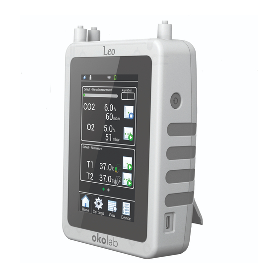
- Page 1 Handheld Analyzer for IVF Applications Manual IST1446_REV05 SV 3.1.64.0...
- Page 2 This page was left blank...
-
Page 3: Table Of Contents
EMBEDDED IN 5.11 P LEO) ................................... 11 EMBEDDED IN OPTIONAL PARTS ................................. 13 T1-MODULE ......................................13 T2-MODULE ......................................13 LEO CONNECTION PORTS ..............................14 PRELIMINARY OPERATIONS............................. 15 ..................................... 15 HARGE THE BATTERY & T .................................... 16 IME SETTING ....................................... 16... - Page 4 CO2-O2-MODULE EXTRACTION ........................... 83 PUMP EXTRACTION ................................. 85 SUPPORT ..................................... 89 TROUBLESHOOTING ................................ 90 TECHNICAL SPECIFICATION ............................91 21.1 LEO ..........................................91 21.2 CO2-O2-MODULE ....................................92 21.3 T1-MODULE ......................................93 21.4 T2-MODULE ......................................93 FIGURE LIST ..................................94 MANUAL REVISION TABLE ................................ 96...
-
Page 5: Symbol Description
Symbol description This paragraph describes the symbols used in this manual and on the product label. Symbols used in this manual and on the product The following symbols identify important information: CAUTION or WARNING or IMPORTANT: This symbol warns of circumstances or practices that can affect the instrument’s functionality. -
Page 6: Safety Notes
Safety Notes In order to achieve maximum performance and to ensure proper operation of your new equipment, please read carefully the following safety notes and the instructions. If you have any question, please contact Okolab. − This equipment must be used only as intended and described in this Manual. -
Page 7: Regulatory Compliance
The product must not be disposed as a general household waste. At the end of the product’s life, take the product to a collection point designed for recovering and recycling of electrical and electronic devices. In case of doubt, please return the product to Okolab s.r.l. for proper treatment. -
Page 8: Preface
LEO can perform both single measurement and extended time logging, storing the data in its local memory. LEO allows organization of the stored data, associating a label to each device. You can store up to 40 devices labels. The stored data to be downloaded through the micro USB port, and analyzed by using the free LEO DATA IMPORT Excel Macro. -
Page 9: Sensor Modules
Sensor Modules The available Sensor Modules (see paragraph 10 and paragraph 13.4) − CO2-O2-MODULE (embedded into LEO) − T1-MODULE (external) − T2-MODULE (external) − CO2-PPM-MODULE (external) − HUMIDITY-MODULE (external) − FLOW-RATE-MODULE (external) Figure 2. LEO with T1-MODULE and T2-MODULE... -
Page 10: Supplied Equipment
Supplied equipment Figure 3 shows the Hard Case containing LEO’s equipment. The optional and spare parts can be purchased from Okolab s.r.l. Please see www.oko-lab.com or contact info@oko-lab.com for more details. Figure 3. LEO Hard Case. LEO. Hand-held meter for IVF applications. -
Page 11: Power Supply
LEO is powered by a rechargeable battery. A power supply is included with the device for charging the battery from a power outlet. Connect the USB cable between the LEO MICRO-USB port and the power adapter to charge the internal battery in LEO (see Figure 4). -
Page 12: Soda Lime Kit
The connector marked in red is the Gas Outlet port for the Moisture Trap (2 in Figure 7). Please use the Tube-A to connect the Gas Outlet port of the Moisture Trap to the Gas Inlet port of LEO (see Configuration b in Figure 46 for the measurements in Diffusion Mode or Configuration b in Figure 48 for the measurements in Aspiration Mode). -
Page 13: Otg-Cable
FRONT BA CK Figure 7. Moisture Trap. OTG-Cable The OTG Cable (G in Figure 3) can be used to download data stored on LEO to a USB Key. USB Key is not supplied. Figure 8. OTG Cable Fitting Tubes Okolab supplies 5 different types of reduction fitting tubes (I in Figure 3) allowing the compatibility of its tubes with many sampling gas ports of the incubators. -
Page 14: Tube-A
Tube-A Tube-A (K in Figure 3) is used to connect the Gas Inlet connector of LEO to the Tube-B if the gas to be sampled is dry or to the Gas Outlet connector of the Moisture Trap, if the gas is humid. -
Page 15: Additional Tubes
The pump is a micro diaphragm pump that guarantee the desired gas flow rate (from 60 ml/min to 260 ml/min). The default flow rate is 150 ml/min. The pump is designed for easy extraction from LEO, see paragraph 18). Figure 13 shows an image of the pump inside LEO. - Page 16 Figure 13. Pump...
-
Page 17: Optional Parts
T2-MODULE T1-MODULE The T1-Module (see Figure 14) is a calibrated temperature probe that can be read and displayed by LEO. The T1-MODULE has an external diameter of 0.13 mm and it’s suitable for temperature measurements of benchtop and hightop incubators where the temperature monitoring port has a diameter smaller than 2mm. T1-MODULE stores calibration data in its own local memory Tip ►... -
Page 18: Leo Connection Ports
To turn LEO on: press and hold the power button for 2 seconds. To turn LEO off: press and hold for 2 seconds the power button, and tap OK to confirm. Press and hold for 5 seconds the power button to start the Touchscreen Calibration procedure (see paragraph 15). -
Page 19: Preliminary Operations
Battery full symbol appears at the top of display. Figure 17. Homepage - battery If LEO is switched off, press the power button to display the battery charging status and the percentage of battery charge (see Figure 18). -
Page 20: Date & Time Setting
Date & Time setting When turning LEO on for the first time, Date & Time have to be set because the current date & time values are stored with every reading. To change Date & Time and their format see paragraph 9.3.5.1. -
Page 21: Navigation Menu
1. Wet/Dry button: to set the Dry or Wet Mode. See paragraph 10.1.5. 2. Pump/Diffusion button. Press Pump button to run the pump and draw the gas sampling into LEO 3. CO2-O2 Single Point Measurement: to start a Single Point measurement of CO2 -O2 gas concentration. - Page 22 23. Battery Status with percentage of battery charge 24. Time. 25. USB Icon: Displayed when a USB key is connected to LEO for data download. See paragraph 12.2. 26. RH: Relative humidity measurements. Not displayed if no HUMIDITY-MODULE is connected to LEO 27.
-
Page 23: Alarm Icons And Meanings
Alarm Icons and meanings LEO can display different alarms, which are identified by the Alarm Icons displayed on the Homepage during an alarm condition. The Yellow Warning Alarm Icon (15 in Figure 19) indicates that the current CO2 or O2 value is out of the range defined in the alarm subpage (see paragraph 9.3.4) during the... -
Page 24: Device
Device LEO allows associating a label to each device connected. To choose an existing device press the Device icon in Settings page (see Figure 21 a) and select the device-name for which data shall be stored (see Figure 21 b). -
Page 25: Calibration
(as shown in Figure 23 a) you can calibrate the available sensors and you can display stored calibration data. Figure 23. Calibration page (a – b). Note ► External sensor modules’ icons are automatically disabled if sensor modules are not connected to LEO. -
Page 26: Pump
9.3.3 Pump Figure 24 shows the internal pump subpages. By pressing Pump icon (see Figure 24 a), you can read the remaining lifetime of the pump and its current flow rate. Press Advanced (see Figure 24 b) to set a different flow rate (from 60 to 260 ml/min) (see Figure 24 c). Tip ►... - Page 27 3. Press on Continue (see Figure 27 a). The pump starts operating and aspirating air. The pressure inside LEO begins to rise. Wait until aspiration step is completed (see Figure 27 b). Figure 27 c appears. Figure 27. How to set Pump Leak Test – aspiration step (a – b - c).
- Page 28 4. Put the cap on LEO gas inlet port with icon (see Figure 28) and press on Continue (see Figure 29 a). Wait stabilization time (see Figure 29 b), during this time the pump is not running. Wait until the Leakage evaluation step is completed (see Figure 29 c).
-
Page 29: Alarm
If the Leak test failed, a leakage in the pump is present and a red label showing FAILED appears. Make sure that caps are well inserted into LEO’s ports and repeat the Leak test. If the Leak test failed again please contact Okolab support at support@oko-lab.com. -
Page 30: System
5. Repeat the steps 1-4 to insert the alarm parameters for the variables on which you want to active an alarm. Note ► External sensor modules’ icons are automatically disabled if sensor modules are not connected to LEO. 9.3.5 System Figure 32 b shows the System subpage. -
Page 31: Date & Time
2. Press Change (see Figure 33 b) to enter the Set Date page. Tip ►Okolab recommends to check the Date & Time Settings the first time you turn LEO on because the current Date & Time values are stored with every reading. -
Page 32: Power Saving
Press the Power saving icon (see Figure 36 a) to set Low brightness feature and Stand By feature. Low brightness feature is enabled by default. Set the time period after which LEO will reduce the display’s brightness by 15%. Note ►Display’s brightness is automatically reduced when the remaining battery power is less than 5%. -
Page 33: Memory
System Information, as shown in Figure 38 a. This page contains the information related to LEO serial number and version (see Figure 38 b). Click on the right arrow icon to move to sensor module information panel. -
Page 34: Display
Tip ► Please have this information handy when contacting Okolab for support. Figure 38. System information (a – b). 9.3.6 Display Press the Display icon to modify the display options (see Figure 39 a). As shown in Figure 39 b, in the Display page it is possible to set: Brightness: to modify the display brightness (see paragraph 9.3.6.1). -
Page 35: Brightness
9.3.6.1 Brightness To modify the display Brightness, press the icon (see Figure 40 a) and use the slide bar displayed or simply press + and -, as shown in Figure 40 b. Press Save to confirm or Cancel to undo. Figure 40. -
Page 36: Touchscreen
9.3.6.3 Touchscreen To change the touch sound frequency, press the Touchscreen icon (see Figure 42 a) and slide your finger along the Buzzer frequency bar (1 in Figure 42 b) or simply press + and -, then press Save to confirm or Cancel to undo. -
Page 37: Factory Reset
Figure 43. Units (a – b) 9.3.8 Factory Reset Press on Factory Reset icon (see Figure 44 a) to restore the default factory settings, a pop-up dialog box appears (see Figure 44 b). Press Ok to start Factory Reset or Cancel to undo (see Figure 44 b). Figure 44. -
Page 38: 10 Co2-O2 Measurement Process
Aspiration Mode, with pump running. Use Aspiration Mode when the sampling gas is at atmospheric pressure. Tip ► The default value of the gas flow rate sucked by LEO is 150 ml/min. To change this value, see paragraph 9.3.3. To start a gas measurement process, press the ON/OFF button and wait until the Warming up time ends. - Page 39 46, Configuration a and 5 in Figure 46, Configuration b) 5. Okolab recommends the use of a purge tube attached to LEO gas outlet port (5 in Figure 46, Configuration a and 6 in Figure 46, Configuration b ). You can use the supplied additional tube as tube for purging.
- Page 40 TUBE B To dr y incubator Configuration a LEO connections in Diffusion Mode TUBE A TUBE B To wet incubator Configuration b LEO connections in Diffusion Mode Figure 46 . LEO Connections in Diffusion Mode (Configuration a - Configuration b).
- Page 41 48, Configuration a and 5 in Figure 48, Configuration b) 5. Okolab recommends the use of a purge tube attached to LEO gas outlet port (5 in Figure 48, Configuration a and 6 in Figure 48, Configuration b ). You can use the supplied additional tube as tube for purging.
- Page 42 TUBE A TUBE B To dr y incubator Configuration a LEO connections in Aspiration Mode TUBE A TUBE B To wet incubator Configuration b LEO connections in Aspiration Mode Figure 48. LEO Connections in Aspiration Mode (Configuration a - Configuration b).
- Page 43 (see Figure 49 a) to select the Aspiration Mode (see Figure 49 b). Once you have followed the step above, LEO is ready to be used in Aspiration Mode. See paragraph 10.1.3 to start a Single Point Measurement or 10.1.4 to start a gas measurements logging.
- Page 44 Figure 50. CO2-O2 single point measurement (a – b - c). During the CO2-O2 Single Point Measurement, CO2 and O2 gas concentration values appear on the Homepage. The CO2-O2 Single Point Measurement icon becomes (see Figure 50 c). 3. Press the View icon to view data stored (see Figure 51 a).
- Page 45 Note ► If no device is selected, the data are stored on the current device shown on the Homepage (1 in Figure 52 a). 2. Press the CO2-O2 Logging icon (see Figure 52 a). The CO2-O2 Logging Setting is shown. 3.
- Page 46 The Wet Mode is a LEO feature allowing you to set the incubator temperature and relative humidity values. LEO will correct the CO2 and O2 values by accounting for the real water content of the gas drawn from the incubator.
- Page 47 11.1 T Modules – Preliminary Operations Follow the instructions below to connect T1 and T2-modules to LEO. 1. Connect T1-MODULE (or T2-MODULE) to one of the probe connectors on the top of LEO, see Figure 54 a. The reading temperature value is immediately shown.
- Page 48 11.2 Temperature Single Point Measurement After connecting the temperature module (T1 or T2-MODULE), follow the instructions below to start a temperature Single Point Measurement. 1. Select the Device for which data has to be stored (see paragraph 9.3.1). Note ► If no device is selected, the data is stored on the current device shown on the home page (1 in Figure 55 a).
- Page 49 Note ► If no device is selected, the data are stored on the current device shown on the homepage (1 in Figure 56 a). Tip ► During a gas measurement, you can start a temperature measurement and select a different Device for which temperature data shall be stored.
- Page 50 Completed Completed Completed Figure 57. Temperature logging: view data 6. Press the View icon to view the data stored (see Figure 57 b). More details are reported in chapter...
- Page 51 12 Reading Data LEO allows storing sensors’ measurements and then to view (see paragraph 12.1), download (see paragraph 12.2) or delete (see paragraph 12.3) the stored data. 12.1 Viewing Data To view the collected Data, please follow the instructions below.
- Page 52 T1/T2, if the reading refers to a temperature measurement with T1 and/or T2-MODULE (only if you used a T1 and or T2-MODULE purchased separately). In addition to the measurement type, LEO also shows the number of the measurements (3 in Figure 60) for each measurement.
- Page 53 12.2 Downloading Data LEO is equipped with local memory to store sensor modules’ readings. These data can be downloaded on a USB flash drive on user request. To download the stored data of all devices, stored in a precise time interval, follow the instructions below: 1.
- Page 54 Figure 62. Download Data. Figure 63. USB Icon displayed when a USB key is connected to LEO. 2. Press the View icon to open the View Data page (see Figure 64 a). 3. Press the icon to access to the Download/Delete Data page (see Figure 64 b).
- Page 55 Figure 64. How to Download Data (a – b – c). Tip ► To download all the data stored on LEO internal memory, flag All checkbox (1 in Figure 65) and Download checkbox (2 in Figure 65). Then press OK to confirm (3 in Figure 65).
- Page 56 4. Enable the Download check box (1 in Figure 66 c) and then press OK to download the selected data to the USB Key (2 in Figure 66 c). Figure 66. How to Download Data for a single device (a – b - c). To download a single reading of a single device, connect the USB key to the MINI-USB port (see Figure 62) and follow the instructions below: 1.
- Page 57 Figure 68. Downloaded files on the pen drive Tip ► Please, use Microsoft Excel to open the downloaded .txt files. You can download LEO DATA IMPORT Excel Macro from Okolab website www.oko-lab.com. LEO DATA IMPORT Excel Macro helps you to organize your stored data.
- Page 58 Figure 69. Leo Data Import Excel Data Press Select folder and choose the folder that contains LEO data. LEO Data Import Excel Macro automatically creates a new Excel file in the same folder with LEO data. The new excel file contains all LEO data automatically organized.
- Page 59 Tip ► To delete all the data stored on LEO internal memory, flag All checkbox (1 in Figure 71) and Delete checkbox (2 in Figure 71). Then press OK to confirm (3 in Figure 71). Figure 71. How to Delete all data stored on LEO.
- Page 60 To delete a single reading of a single device follow the instructions below: 1. Press the device name (see Figure 72 a). 2. Press a single reading (see Figure 73 a) and then press the icon in the page that opens (see Figure 73 b).
- Page 61 13 CO2-O2-MODULE Calibration Press on Settings icon to access to the Settings subpage (see Figure 75 a). Press on Calibration icon (see Figure 75 b) and select CO2/O2 icon (see Figure 75 c). The CO2/O2 Calibration page appears as in Figure 76). Figure 75.
- Page 62 To improve LEO reading accuracy, it is possible to perform CO2/O2 User Calibration using span gases. If you want to achieve the best accuracy in the sensors’ measurement range 0 – 10%, Okolab suggests to use a certified span gas cylinder with composition similar to the gas used during your working standard conditions.
- Page 63 4. Connect end of the Calibration Kit to the gas cylinder (4 in Figure 79). 5. Okolab recommends the use of a purge tube attached to LEO gas outlet port (5 in Figure 58). The purge tube has to be placed in a well ventilated environment. You can use the supplied additional tube as tube for purging.
- Page 64 5. Okolab recommends the use of a purge tube attached to LEO gas outlet port (5 in Figure 59). The purge tube has to be placed in a well ventilated environment. You can use the supplied additional tube as tube for purging.
- Page 65 3. Connect the red connector (b) of Tube-A to the gas reference at atmospheric pressure (1 in Figure 81). 4. Okolab recommends the use of a purge tube attached to LEO gas outlet port (5 in Figure 79). The purge tube has to be placed in a well ventilated environment. You can use the supplied additional tube...
- Page 66 TUBE A TUBE B Gas at atmospher ic pr essure Figure 81. How to connect LEO during a calibration in Aspiration Mode. 13.2.3 Span Setting Press Span Calibration icon to access to the Span Calibration submenu (see Figure 82 a).
- Page 67 % and O2 at 5.00 %), the Span Gas 3 only for calibrating the CO2 sensor (at 19 %). Figure 83. Span Settings page (a – b). 3. If you use a gas with an overpressure for the CO2/O2 User Calibration, you can calibrate LEO in Diffusion Mode, as shown in Figure 83 b.
- Page 68 Press Continue (see Figure 86 a) to start the Span Calibration after checked the proper span gas cylinder is connected to LEO. During an Auto calibration, you can see CO2 and O2 readings on the display (see Figure 86 b).
- Page 69 During a Manual calibration, you can see the CO2 and O2 readings on the display. Wait until the CO2 and O2 readings became stable. Tip ► Okolab suggests waiting at least 10 minutes before stopping Manual Calibration, if using Okolab Calibration Kit.
- Page 70 View Current icon to view the CO2/O2 User Calibration data. 13.3 Factory LEO allows to delete the last CO2/O2 User Calibration and to restore the factory values. To reset the current sensors calibration: 5. Press the Factory icon (see Figure 89 a).
- Page 71 The first CO2 Zero Reset procedure is performed at our factory. To improve LEO reading accuracy the CO2 Zero Reset should be repeated every thirty days. LEO will remind you every thirty days to perform the CO2 Zero Rest before the CO2/O2 User Calibration and before a CO2 single or logging measurement (see Figure 90 b).
- Page 72 You can decide to use Air or N2 for the CO2 Zero Reset procedure. Tip ►Okolab suggests to start the CO2 Zero Reset using N2, use Air only if N2 is not available. Figure 91. CO2 Zero Reset (a – b).
- Page 73 Soda Lime Kit Figure 94. How to connect LEO during a CO2 Zero Reset procedure with Air. The CO2 Zero Reset procedure takes 15 minutes, the remaining time is shown on the display during the procedure (see Figure 92 c).
- Page 74 CO2 Zero Reset with N2 To start the CO2 Zero Reset procedure using N2, press on N2 as shown in Figure 97 a. Pressing on N2, LEO reminds you to connect a Nitrogen bottle at 1.0 barg (14.5 psig) to LEO. See Figure 97 b.
- Page 75 4. Connect end of the Calibration Kit to the gas cylinder (4 in Figure 99). 5. Okolab recommends the use of a purge tube attached to LEO gas outlet port (5 in Figure 99). The purge tube has to be placed in a well ventilated environment. You can use the supplied additional tube as tube for purging.
- Page 76 5. Okolab recommends the use of a purge tube attached to LEO gas outlet port (5 in Figure 100). The purge tube has to be placed in a well ventilated environment. You can use the supplied additional tube as tube for purging.
- Page 77 TUBE A Figure 100. How to connect LEO to N2 cylinder with flow regulator. After connecting LEO to N2 cylinder, press Ok (see Figure 97 b). A pop-up with the procedure progress appears, see Figure 97 c. At the end of the CO2 Zero Reset procedure with N2, a pop-up message is shown as in Figure 101. Press Ok to return to the CO2/O2 Calibration page.
- Page 78 Figure 102. CO2 Zero Reset procedure with N2 has failed. 13.5 Offset LEO allows also calibration of the CO2 and O2 sensors by using an external gas meter (not hereby provided). To run the CO2/O2 User Calibration, it is necessary to follow the instructions below: 1.
- Page 79 O2 values. 2. Connect LEO to the incubator at the same point in which you have measured by the external gas meter (see paragraph 10 to connect LEO to the incubator) and start an Auto or a Manual gas measurement.
- Page 80 Figure 105. How to insert CO2/O2 Reference value (a - b). Note ►When you start the CO2/O2 User Calibration procedure, LEO deletes all stored Offset values.
- Page 81 14 T1 and T2 modules Calibration LEO is equipped (on request) with one or two factory calibrated temperature modules (T1-MODULE and/or T2 Module). The factory calibration certificate is included in electronic format in the T1 and T2 modules and can be seen in the T1/T2 calibration pages (see paragraph 14.1).
- Page 82 (possibly a water bath) then follow the instructions below: 1. Connect the temperature module (T1-MODULE or T2-MODULE) that you want to calibrate to LEO. 2. Immerse the certified thermometer and the tip of T1-MODULE (or T2-MODULE) in water bath.
- Page 83 36.8 36.8 Figure 108. T1 Calibration: start multi-point calibration (a – b - c). 8. When you finish the calibration, an overview appears as in Figure 109. Click on Save to complete the calibration or Cancel to undo. 25.00 30.00 37.00 40.00 50.00...
- Page 84 Figure 110. T1 Calibration: Factory Reset (a – b).
- Page 85 15 Touchscreen Calibration Keep pressed the ON/OFF button for 3 seconds to start the Touchscreen Calibration (see Figure 111). While holding the ON/OFF button, the pop-up message shown in Figure 112 a appears. Tap the blue calibration dots until the calibration is complete (see Figure 112 b). Front view Right view Figure 111.
- Page 86 16 Cleaning & Maintenance Cleaning For a long lifetime and to take full advantage of this product, Okolab recommends cleaning the product periodically. Please, follow the instructions below to clean LEO: − Use a polishing cloth or dry cloth to wipe off dust and dirt.
- Page 87 Fasten the screws (1 in Figure 114, c and 2 in Figure 114, d) by using a hexagonal key (1.5mm). Put the rear cover on LEO and fasten the screw by using a hexagonal key (2.5mm), as shown in Figure 114,f.
- Page 88 Figure 114. CO2-O2-MODULE insertion...
- Page 89 18 Pump extraction The pump is designed for easy extraction from LEO. It has to be replaced when its lifetime reaches the 1000 hours of operation. As a first step, disconnect CO2-O2-MODULE. Follow the instructions below to extract CO2-O2-MODULE: Loosen the screw by using a hexagonal key (2.5mm), as shown in Figure 115, a. Then lift up and remove the rear cover of LEO (see Figure 115, b).
- Page 90 Replace the pump with new pump ordered from Okolab. Reconnect the electrical connector of the new pump (see Figure 117, a). Connect the inlet and outlet tubes (see Figure 117, b). Connect LEO tube marked by (see Figure 117, c) to the inlet port of the pump (1 in Figure 117, d).
- Page 91 Fasten the screws (1 in Figure 118, c and 2 in Figure 118, d) by using a hexagonal key (1.5mm). Put the rear cover on LEO and fasten the screw by using a hexagonal key (2.5mm), as shown in Figure 118,f.
- Page 92 Figure 118. CO2-O2-MODULE insertion after pump replacement...
- Page 93 You can request a remote support session anytime. Please, do not hesitate to contact Okolab for any further commercial information or technical support. HARDWARE SUPPORT: sibillo@oko-lab.com Phone +39 081 806 3470...
- Page 94 20 Troubleshooting The table below shows some frequently asked questions. Please contact Okolab if you need assistance. Solution Effect Main Causes Secondary Causes Gas flow rate sent to Sent to LEO a gas flow rate higher than 60 Auto measurement...
- Page 95 21 Technical Specification 21.1 LEO Technical Data Maximum pressure 1300 mbar (19 psig) Operating flow rate Min 30 ml/min – Max 400 ml/min Barometric Pressure sensor 500 – 1200 mbar Measuring range Data Storage 300 measurements Data Download Micro USB to USB OTG host adapter...
- Page 96 21.2 CO2-O2-MODULE CO2 Sensor – Technical Data Sensor type Non Dispersive InfraRed detector (NDIR) Measurement Range 0-20% Accuracy ± (1% of Full Scale +2% Reading) in the range 0-10% ± (2% of Full Scale +3% Reading) in the range 11-20% Response Time, T <...
- Page 97 21.3 T1-MODULE Technical Data Sensor K-type Thermocouple. PFA-insulated: Length 2m; OD: 0.13mm Range 0-60°C Accuracy (from 20 to 50°C) ± 0.1°C Figure 119. T1-MODULE-Technical drawing 21.4 T2-MODULE Technical Data Sensor PT1000 RTD Class A. Probe Length: 150mm; OD: 2.0mm; Cable Length: 1m Range 0-60°C Accuracy (from 20 to 50°C)
- Page 98 Figure 44. Factory reset (a – b)........................................33 Figure 45 . LEO is warming up........................................34 Figure 46 . LEO Connections in Diffusion Mode (Configuration a - Configuration b)..................36 Figure 47. How to select the Diffusion Mode (a – b)................................. 37 Figure 48.
- Page 99 Figure 92. CO2 Zero Reset with Air (a – b - c)..................................68 Figure 93. Soda Lime Kit connected to Tube-A..................................69 Figure 94. How to connect LEO during a CO2 Zero Reset procedure with Air..................... 69 Figure 95. CO2 Zero Reset procedure with Air completed............................70 Figure 96.
- Page 100 Manual Revision Table Revision Number Addition of changes Date Redaction June 2018 Review July 2018 New redaction November 2018 New features May 2019 Changes in hardware September 2019 Changes in tubes October 2019...
- Page 101 WARRANTY Okolab S.r.l. warrants “LEO” to be free of defects in materials and workmanship for a period of one year starting from invoice date. If the unit malfunctions, it must be returned to the factory for evaluation. If the equipment has to be returned to the factory, please ensure that is carefully and properly packed. Okolab S.r.l.
Need help?
Do you have a question about the LEO and is the answer not in the manual?
Questions and answers