Table of Contents
Advertisement
Advertisement
Table of Contents

Related Manuals for Elster Instromet 6 Series


Summary of Contents for Elster Instromet 6 Series
- Page 1 73023465_A_EN i 2016-02-09 Doc: 10000050186...
- Page 2 Elster GmbH Steinern Strasse 19-21 D - 55252 Mainz-Kastel, Germany Tel.: +49 6134 6050 Fax: +49 6134 605 566 E-Mail: info@elster-instromet.com Page 2 of 38 Safety Instructions UFM Series 6...
-
Page 3: Table Of Contents
Contents General Information About these Instructions Limitation of Liability Text Labelling 2.1.1 Presentation of Safety and Risk Instructions 2.1.2 Paragraph Formats 2.1.3 Character Formats Application and Operation System 3.2.1 SPU - Special Conditions for Safe Use 3.2.2 SPU – Label Hazardous Situations Storage and Transportation Installation... - Page 4 Contents Electrical Parameters Index Appendix I – References Annex A - Control Drawing (FM) Annex B - Control Drawing (CSA) Annex C - Safety Prescriptions Page 4 of 38 Safety Instructions UFM Series 6...
-
Page 5: General Information
General Information 1 General Information 1.1 About these Instructions This manual contains safety instructions for installation, operation, and maintenance of the Ultrasonic Flow Meter (UFM) Series 6, models atom plus Q.Sonic , Q.Sonic , CheckSonic, Vx.Sonic and FlareSonic. In addition to providing essential information for proper operation and maintenance of the product, this manual offers important instructions to prevent accidents and serious damage in all stages of the product’s lifespan;... - Page 6 General Information The warranty provisions stipulated in the manufacturer's Terms of Delivery are applicable to the product. The manufacturer shall have no obligation in the event that: Repair or replacement of equipment or parts is required through normal wear and tear, or by necessity in whole or part by catastrophe, or the fault or negligence of the purchaser;...
-
Page 7: Text Labelling
Text Labelling 2 Text Labelling This manual employs consistent visual cues and standard text formats to help you easily locate and interpret information. This information will help you quickly identify relevant content. 2.1.1 Presentation of Safety and Risk Instructions Hazard Warnings Hazard warnings indicate hazardous situations which may result in material damage and bodily harm or even death if disregarded. -
Page 8: Paragraph Formats
Text Labelling 2.1.2 Paragraph Formats This triangle prompts you for an action. ► This character will show you the immediate result of your action. Example Multi-row examples are marked by two continuous blue lines and the keyword “Example”. 2.1.3 Character Formats Example ... -
Page 9: Application And Operation
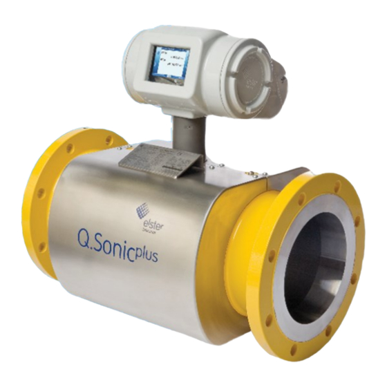
Application and Operation 3 Application and Operation 3.1 System The ultrasonic flow meter comprises of the following main parts as listed below and seen in Figure 3-1. The flow cell (in yellow) is the part of the ultrasonic flow meter that is mounted in the piping system. All other components are mounted on the flow cell. - Page 10 Application and Operation Flow Meter components: The Signal Processing Unit (SPU) – houses the flow meter electronics. Two Ultrasonic Transducers per flow measurement path. The spoolpiece (Flow Cell) designed for gas flow measurement. An optional Pressure Sensor. ...
-
Page 11: Spu
Application and Operation 3.2 SPU The Signal Processing Unit (SPU) houses the flow meter electronics and comprises the following user interfaces: SPU label (see the following paragraphs) Electrical user connections ( see Chapter 4 Installation Chapter 5 Electrical Parameters) ... - Page 12 Application and Operation Additional label information depending on the applicable approval (see following label examples) Please see below for an explanation of each label type using an Ultrasonic Plus Flow Meter Series 6 Q.Sonic model as an example. ATEX Certification The explosion proof housing has the following ATEX certification information: ...
- Page 13 Application and Operation Figure 3-3: Example of an IECEx Label FM Certification The explosion proof housing has the following FM certification information: Explosion proof for Class I, Division 1, Group A, B, C and D Intrinsically safe for Class I, Division 1, Group A, B, C and D ...
- Page 14 Application and Operation CSA Certification The explosion proof housing has the following CSA certification information: Explosion proof for Class I, Division 1, Group B, C and D T6 Ex d ia [ia] IIB + H2 T6 -50 °C < Tamb < +60 °C ...
-
Page 15: Hazardous Situations
Application and Operation 3.3 Hazardous Situations Read the instruction manual before operating device. Never open the explosion proof box with the electronics inside when meter is energized. Do not open the enclosure if explosive atmosphere may be present. ... -
Page 16: Installation
Installation WARNING! Obey the rules and regulations that apply to hazardous area operations and those with respect to custody transfer regulations (sealing). 4 Installation 4.1 General It is the user’s responsibility to ensure that the installation complies with appropriate regulations, including those required by applicable certifications. It is highly recommended to install the meter on a vibration free location. - Page 17 Installation National and local regulations; the SPU documentation (this manual, order specification stating the type of entry holes) and on the SPU label; the certificate and manual of the glands; Specifications of the user wiring. It is recommended to use suitable armoured shielded cable to provide protection against mechanical damage and electrical interference.
-
Page 18: System Specifications
Installation WARNING! Do not perform any modification of the products supplied. The volume of the SPU enclosure to fit user glands is less than 2 liters. Unused gland entries must be fitted with suitable certified stopping plugs. ... - Page 19 Installation WARNING! For compliance with EN-IEC 61010 (also harmonized under EU Low Voltage directive 2006/95/EC) the SPU requires an external power supply, limited-energy (< 30 Vdc max. 8A), and reinforced insulation between input and output by the safety transformer and appropriate distance between components on the PCB.
-
Page 20: Dsl / Network Connections (Tb2 & J4)
Installation 4.3.1 DSL / Network Connections (TB2 & J4) DSL Network / Ethernet connections Power over Ethernet Maximum cable core 1.5 mm 4.3.2 Outputs / Communication (TB3) Two configurable opto-coupler outputs, max 30VDC @ 12mA. Two isolated passive/active 4...20mA analogue outputs, 16 bit resolution. -
Page 21: Field Terminal Board
Installation 4.4 Field Terminal Board The field terminal board in the back compartment of the electronics enclosure is for customer connections. Figure 4-1: Field Terminal Board in Electronics Enclosure 4.5 Transducer Connections The Analogue board PCB has a terminal block to connect the transducers for each transducer and the optional pressure sensor. -
Page 22: Pressure Connection
Installation 4.6 Pressure Connection All forged meters bodies sizes 3” (DN80) to 12” (DN300) are supplied with ½” NPT Pr adapters and ½” NPT blind plugs. Adapters and plugs are sealed with PTFE tape and hydrotested with the meter body. After the hydrotest, adapters and plugs are painted together with the meter body. -
Page 23: Electrical Parameters
Electrical Parameters 5 Electrical Parameters Intrinsically Safe Field Terminal Board (see Figure 4-2) Terminals 4-20 mA connection with HART, label “IS_opt_C1” and “IS_opt_C2” circuit (terminals P+ and P-) IS_opt_C1, (for p flow pressure sensor) IS_opt_C2 In type of protection intrinsic safety, with the following maximum values: = 23.1 V = 109 mA... - Page 24 Electrical Parameters Intrinsically Safe Terminals Namur pulse input #1, with label “IS_opt_B1” and “IS_opt_B3” circuit (terminals Z1+ and Z1-): IS_opt_B1, IS_opt_B3 In type of protection intrinsic safety, with the following maximum values: = 9.1 V = 37 mA = 84 mW = 10 mH = 0.5 μF Terminals...
-
Page 25: Index
Index 6 Index ATEX Certification, 12 Non- Intrinsically Safe Terminals, Cathodic Protection, 19 Character Formats, 8 Outputs / Communication (TB3), CSA Certification, 14 Dokuthek, 5, 10 Paragraph formats, 8 DSL / Network Connections (TB2 Power connection (TB1):, 18 & J4), 20 Pressure Connection, 22 Electrical Parameters, 23 References, 26... -
Page 26: Appendix I - References
Appendix I – References Appendix I – References All references listed below can be obtained from Elster. Additionally, most references are available online at: http://www.docuthek.com/. plus UFM Series 6 Q.Sonic Operation and Maintenance Manual SAP Ref.: 73023467 Doc. No.: 10000050188 (last valid revision) UFM Series 6 CheckSonic Operation and Maintenance Manual SAP Ref.: 73023471... - Page 27 Appendix I – References UFM Series 6 Transducer Exchange at Atmospheric Conditions SAP Ref.: 73023472 Doc. No.: 03.200.001.001/02/2 (last valid revision) Retraction Tool NG Transducers SAP Ref.: 73023473 Doc. No.: 03.203.101.001.02/2 (last valid revision) [10] UFM Series 6 Exchanging PCB boards in TIP SAP Ref.: 73023474 Doc.
- Page 28 Page 28 of 38 Safety Instructions UFM Series 6...
-
Page 29: Annex A - Control Drawing (Fm)
Annex A – Control Drawing (FM) Drawing 03.304.001.003.05/2 (FM Approved) UFM Series 6 Safety Instructions Page 29 of 38... - Page 30 Annex A – Control Drawing (FM) Page 30 of 38 Safety Instructions UFM Series 6...
-
Page 31: Annex B - Control Drawing (Csa)
Annex B – Control Drawing (CSA) Drawing 03.304.001.004.05/2 (CSA Approved) UFM Series 6 Safety Instructions Page 31 of 38... - Page 32 Annex B – Control Drawing (CSA) Page 32 of 38 Safety Instructions UFM Series 6...
-
Page 33: Annex C - Safety Prescriptions
Annex C – Safety Prescriptions Ultrasonic Flow Meter Series 6 This annex includes a non-exhaustive list of important safety prescriptions for a Series 6 Ultrasonic Flow Meter. At dispatch the latest version of this Annex is attached to the UFM. For safety reasons it is required to read and understand the entire document to which this Annex belongs: UFM Series 6 Safety Instructions. - Page 34 Annex C – Safety Prescriptions Safety Prescriptions - Ultrasonic Flow Meter Series 6 Read the instruction manuals before handling or operating the device! See Appendix I – References at the back of this manual for a list of all available information. ...
- Page 35 Annex C – Safety Prescriptions (Pr) point adapter (at both ends) and the blind plug shall be replaced with appropriate sealant for the application. Hold Pr point adapter with 30mm wrench while removing blind plug or fitting new connections. ALWAYS CHECK NEWLY MADE CONNECTIONS FOR LEAKS.
- Page 36 Annex C – Safety Prescriptions Use the ultrasonic meter only for its intended application. Restrict to media and pressure & temperature limits. Never use an ultrasonic meter outside of these limits (for information see name plate). It is not allowed to perform repair and maintenance activities on an operating ultrasonic meter.
- Page 37 Annex C – Safety Prescriptions Always use the correct tools and parts. Never use pneumatically powered tools, electrically powered tools or hydraulically powered tools to perform retraction of an Ultrasonic Transducer. Always leak test the meter after installation. ...
- Page 38 Annex C – Safety Prescriptions Types of coatings that may be applied in the spoolpiece of an ultrasonic flow meter: VCI Foam: Vapour Corrosion Inhibitor (VCI) foam has been applied if its type reference is mentioned above. The foam needs to be removed before installation.
Need help?
Do you have a question about the 6 Series and is the answer not in the manual?
Questions and answers