
Subscribe to Our Youtube Channel
Related Manuals for Lanner NCA-4012


Summary of Contents for Lanner NCA-4012
- Page 1 Network Appliance Platform NCA-4012 User Manual Version: 1.0 Date of Release: 2020-09-02...
- Page 2 - assumed to be qualified in the servicing of computer equipment, such as professional system integrators, or service personnel and technicians. The latest version of this document can be found on Lanner’s official website, available either through the product page or through the Lanner Download Center page with a login account and password.
- Page 3 Lanner Q&A page for diagnostic procedures and troubleshooting steps. Technical Support In addition to contacting your distributor or sales representative, you could submit a request to our Lanner Technical Support at http://www.lannerinc.com/technical-support where you can fill in a support ticket to our technical support department.
- Page 4 Contact Information Taiwan Corporate Headquarters China Lanner Electronics Inc. Beijing L&S Lancom Platform Tech. Co., Ltd. 7F, No.173, Sec.2, Datong Rd. Xizhi District, Guodong LOFT 9 Layer No. 9 Huinan Road, New Taipei City 22184, Taiwan Huilongguan Town, Changping District, Beijing 立端科技股份有限公司...
- Page 5 Federal Communication Commission Interference Statement This equipment has been tested and found to comply with the limits for a Class A digital device, pursuant to Part 15 of FCC Rules. These limits are designed to provide reasonable protection against harmful interference in a residential installation.
- Page 6 Safety Guidelines Follow these guidelines to ensure general safety: Keep the chassis area clear and dust-free during and after installation. Do not wear loose clothing or jewelry that could get caught in the chassis. Fasten your tie or scarf and roll up your sleeves.
- Page 7 an explosion. Leaving a battery in an extremely high temperature environment can result in an explosion or the leakage of flammable liquid or gas. A battery subjected to extremely low air pressure may result in an explosion or the leakage of flammable liquid or gas.
- Page 8 The installation of this product must be performed by trained specialists; otherwise, a non-specialist might create the risk of the system’s falling to the ground or other damages. Lanner Electronics Inc. shall not be held liable for any losses resulting from insufficient strength for supporting the system or use of inappropriate installation components.
- Page 9 Electrical Safety Instructions Before turning on the device, ground the grounding cable of the equipment. Proper grounding (grounding) is very important to protect the equipment against the harmful effects of external noise and to reduce the risk of electrocution in the event of a lightning strike. To uninstall the equipment, disconnect the ground wire after turning off the power.
- Page 10 This equipment must be grounded. The power cord for the product should be connected to a socket- outlet with earthing connection. Cet équipement doit être mis à la terre. La fiche d'alimentation doit être connectée à une prise de terre correctement câblée Suitable for installation in Information Technology Rooms in accordance with Article 645 of the National Electrical Code and NFPA 75.
-
Page 11: Table Of Contents
Table of Contents Main Features ..........................13 Package Content ......................... 13 Ordering Information ......................... 13 System Specifications ......................... 14 Front Panel ..........................15 Rear Panel ........................... 16 Motherboard Information ......................17 About the CPU and Heatsink ...................... 32 Installing the IPMI Card ......................33 Installing the mSATA........................ - Page 12 Warranty Policy .......................... 78 RMA Service ..........................78 RMA Service Request Form ......................79...
-
Page 13: Main Features
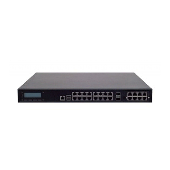
The NCA-4012 is a 1U 19” rackmount network appliance designed for optimal networking and virtualization performance. Its optimization capabilities are made possible by Intel®’s Xeon® D-1548 4 or 16-core CPU, codenamed Broadwell-DE, delivering exceptional computing performance, abundant LAN interface, redundant PSUs, configurable system memory and scalable storage options. -
Page 14: System Specifications
System Specifications Form Factor 1U 19” Rackmount Processor Options Intel® Xeon® D-1500 4~16 Cores (Broadwell-DE) CPU Socket Onboard Platform Chipset Security Acceleration BIOS AMI SPI Flash BIOS DDR4 2400 MHz REG, ECC or Non-ECC UDIMM Technology System Memory R-DIMM: 64GB / ECC: 32GB Max. -
Page 15: Front Panel
Front Panel System Power System Status Activity Description LCM Panel With four keys System Power If the LED is on, it indicates that the system is powered on. If it is off, it indicates that the system is powered off. Status: This LED is programmable. -
Page 16: Rear Panel
Rear Panel Description PCIe Slot 1x PCIex8 HH/HL slot (Optional) 2x Cooling fans Cooling Fan Power Switch Flip to power on the system Redundant PSU 2x swappable Redundant PSUs... -
Page 17: Motherboard Information
Motherboard Information The block diagram indicates how data flows among components on the motherboard. Please refer to the following figure for your motherboard’s layout design. Optional Optional PCIE x4 PCIE x4 B to B Con B to B Con PCIE x4 PCIE x4 Intel I350-AM4 Intel I350-AM4... - Page 18 The motherboard layout shows the connectors and jumpers on the board. Refer to the following picture as a reference of the pin assignments and the internal connectors. ATX2 FAN2 FAN1 JCPLD1 JCMOS1 JVGA1 COMA1 JTPM1 J80PORT1 JSPIROM1 JSATA1 JSATA2 JOPMA1 ATX1 CONN2 JRERSET1...
- Page 19 The pin headers on the motherboard are often associated with important functions. With the shunt (Jumper) pushed down on the designated pins (the pin numbers are printed on the circuit board, surrounding the pin header), a certain feature can be enabled or disabled. While changing the jumpers, make sure your system is turned off.
- Page 20 NM-4010IG401 I/O board bypass flash jump setting pin header(J3) Inphi 10G PHY debug port pin header(J9) (J10) (JRESET1): Select front-panel reset option (1-2) Hardware Reset (2-3) Software Reset (Default) DESCRIPTION BTN_SYS_RESET# FP_RESET# SW_RST_GP5#...
- Page 21 TPM module pin header (JTPM1) 80 Debug port(J80PORT1)
- Page 22 SATA Connector(JSATA1&2) mSATA connector (JMSATA1)
- Page 23 NM-4010IG401 I/O board connector...
- Page 24 (J1&J2) : 2 x 50-pin I/O board connectors, for jointing with I/O board NM-4010IG401. DESCRIPTION DESCRIPTION P3V3 P12V P3V3 P12V P3V3 PCH_SLOT3_A8 PCIESLOT3_I350A_RST# P3V3 PHY_WAKE# SLT3A_SCLK2 CLK100_PCIE_SOLT3_1P SLT3A_SDAT2 CLK100_PCIE_SOLT3_1N IO_LAN12GND IO_LAN34GND IO_P0_S0_1 IO_P1_S0_1 IO_P0_S0_2 IO_P1_S0_2 PCIE_CTX_C_SLOT3RX_P0 PCIE_SLOT3TX_C_CRX_P0 PCIE_CTX_C_SLOT3RX_N0 PCIE_SLOT3TX_C_CRX_N0 PCIE_CTX_C_SLOT3RX_P1 PCIE_SLOT3TX_C_CRX_P1 PCIE_CTX_C_SLOT3RX_N1 PCIE_SLOT3TX_C_CRX_N1...
- Page 25 J2 : DESCRIPTION DESCRIPTION P3V3 P12V P3V3 P12V P3V3 PCH_SLOT3_A8 PCIESLOT3_I350B_RST# P3V3 PHY_WAKE# SLT3B_SCLK3 CLK100_PCIE_SOLT3_2P SLT3B_SDAT3 CLK100_PCIE_SOLT3_2N IO_LAN56GND IO_LAN78GND IO_P2_S0_1 IO_P3_S0_1 IO_P2_S0_2 IO_P3_S0_2 PCIE_CTX_C_SLOT3RX_P4 PCIE_SLOT3TX_C_CRX_P4 PCIE_CTX_C_SLOT3RX_N4 PCIE_SLOT3TX_C_CRX_N4 PCIE_CTX_C_SLOT3RX_P5 PCIE_SLOT3TX_C_CRX_P5 PCIE_CTX_C_SLOT3RX_N5 PCIE_SLOT3TX_C_CRX_N5 PCIE_CTX_C_SLOT3RX_P6 PCIE_SLOT3TX_C_CRX_P6 PCIE_CTX_C_SLOT3RX_N6 PCIE_SLOT3TX_C_CRX_N6 PCIE_CTX_C_SLOT3RX_P7 PCIE_SLOT3TX_C_CRX_P7 PCIE_CTX_C_SLOT3RX_N7 PCIE_SLOT3TX_C_CRX_N7...
- Page 26 CPLD Flash pin header (JCPLD1) ATX Power connector 24P(ATX1) ATX Power connector 4P(ATX2)
- Page 27 CPU Fan (FAN1&2) LCM module connector(JLCM1) Power button (SW1) Power pin header(CONN2)
- Page 28 SPI ROM flash pin header(JSPIROM1) VGA pin header (JVGA1) COM port pin header (COMA1)
- Page 29 IPMI connector(JOPMA1)
- Page 30 Main board bypass flash connector (J7) PHY I2C debug pin header(J11)
- Page 31 To reduce the risk of personal injury, electric shock, or damage to the system, please remove all power connections to shut down the device completely. Also, please wear ESD protection gloves when conducting the steps in this chapter. After opening the chassis, in order to reveal the entire motherboard, remove the fan duct by unscrewing the six screws indicated in the picture below.
-
Page 32: About The Cpu And Heatsink
About the CPU and Heatsink Since the CPU is soldered onboard, the heatsink and the CPU are pre-installed before shipment. In normal circumstances, no installation or replacement is required. If there is any issue related to CPU overheat or damage, please contact the dealership or distributor where you purchase this appliance. Heatsink... -
Page 33: Installing The Ipmi Card
Installing the IPMI Card This system provides one OPMA slot for installing the IPMI card. Follow these procedures below for installing an IPMI card. 1. Locate the OPMA socket. IPMI Card 2. Align the notch of the card with the socket key in the slot. - Page 34 5. Secure the card with a screw that comes with it. To remove the card, loosen the screw that secures it to the motherboard, push aside the two metal leaves that hold the card to release it from the socket before you can pull it out.
-
Page 35: Installing The Msata
Installing the mSATA The motherboard provides one mSATA slot. Follow the procedures below for installing an mSATA card. 1. Locate the mSATA slot. mSATA 2. Align the notch of the module with the socket key in the slot. Socket Notch 3. -
Page 36: Installing The System Memory
Installing the System Memory Please do follow the memory module installation instructions to install the DIMMs, and make sure Do not mix RDIMMs with LRDIMMs. Using memory modules of the same capacity, speed and from the same manufacturer are highly recommended. -
Page 37: Installing The Nic Module
Installing the NIC Module This system comes with 1 NIC Ethernet module slot for network bandwidth expansion. Please follow the steps for installation. 1. Rotate the two lock-screws counterclockwise and loosen them. PCIe Slot 2. Remove the door and locate the PCIe slot for module insertion. -
Page 38: Installing Disk Drives
Installing Disk Drives The system supports 2 x 2.5” SATA HDDs or SSDs as data storage. Please follow the steps below for installation. 1. Locate the disk drive tray at the corner of the system. Loosen the screw indicated in the picture and slide the tray downwards to have it loosened from the four latching spots. - Page 39 3. Place the tray with HDD/SSD installed back to its original spot inside the system. Remember to aim the four latching holes. Then slide the tray upwards to get it locked and secure it with the original screw. 4. Establish SATA cable connection between the disk drive and the motherboard. JSATA1 JSATA2...
-
Page 40: Replacing Cooling Fans
Replacing Cooling Fans This system supports two cooling fans. To replace a worn-down fan, please follow the steps below. 1. Remove the screws circled below. 2. Apply some force and pull the fan out of its original place. 3. To install a new one, just place the new fan to the original place and apply two screws. 4. -
Page 41: Installing Dc Power Supply
Tma = 40 degrees C, and the altitude of operation = 5000m. The cable should be 16AWG (12A minimum, 72V minimum). If you need further assistance with purchasing the power source, please contact Lanner Electronics Inc. for further information. -
Page 42: Mounting The System
Mounting the System There are two methods for installing this system into a rack. Please contact Lanner’s sales representative to purchase the mounting kits mentioned below: With Mounting Ear Brackets only This method is quick and easy by fixing this system to the front posts of the rack, but it also makes servicing the system more difficult. - Page 43 1. Check the accessory pack for the following items: 1x Screw Pack 2x Ear Brackets 2. Align the bracket to the side of the chassis and make sure the screw-holes are matched, and then secure the bracket onto the chassis with three provided screws.
- Page 44 1. Check the package contents of the Slide Rail Kit. The kit shall include the following items: 1x pack of M4X4L screws (for securing the Rail Brackets on the system) 1x pack of 7.1 Round Hole screws (for securing the system on the rail posts) 2x Slide Rails A rail consists of the following parts:...
- Page 45 5. Align the bracket to the side of the chassis and make sure the screw- holes are matched, and then secure the bracket onto the chassis with Align the screws with the holes indicated on the brackets and the three provided M4X4L screws. screw holes on the side of the chassis.
- Page 46 11. Hold the system with its front facing you, lift the chassis and gently engage the brackets on the system while aligning them with the Inner Rails as shown in the image, and then push the system into the cabinet. 12.
-
Page 47: Bios Setup
BIOS Setup BIOS is a firmware embedded on an exclusive chip on the system’s motherboard. Lanner's BIOS firmware offering including market-proven technologies such as Secure Boot and Intel Boot Guard technology deliver solid commitments for the shield protection against malware, uncertified sequences and other named cyber threats. - Page 48 Setup main page contains BIOS information and project version information. Feature Description BIOS Vendor: American Megatrends Core Version: AMI Kernel version, CRB code base, X64 Compliancy: UEFI version, PI version BIOS Information Project Version: BIOS release version Build Date and Time: MM/DD/YYYY Access Level: Administrator / User System Language English...
- Page 49 Select the Advanced menu item from the BIOS setup screen to enter the “Advanced” setup screen. Users can select any of the items in the left frame of the screen. Feature Options Description PXE Function Disabled Enable Lan2 Enable Lan3 Enable Lan4 PXE Function Enable Lan5...
- Page 50 Trusted Computing (TPM1.2) Feature Options Description Enables or disables BIOS support for a security device. Security Device Enabled By disabling this function, OS will not show Security Support Disabled Device. TCG EFI protocol and INT1A interface will not be available.
- Page 51 NCT6776 Super IO Configuration...
- Page 52 Serial port 1 Configuration Feature Options Description Enabled Serial Port Enables or disables Serial Port 1. Disabled Device Settings IO=3F8h; IRQ = 4...
- Page 53 Serial port 2 Configuration Feature Options Description Enabled Serial Port Enables or disables Serial Port 2 Disabled Device Settings IO=2F8h; IRQ = 3...
- Page 54 Parallel Port Configuration Feature Options Description Enabled Parallel Port Enable or Disable Parallel Port (LPT/LPTE) Disabled Device Settings IO=378h; IRQ = 5...
- Page 55 NCT6776 HW Monitor...
- Page 56 Serial Port Console Redirection Feature Options Description COM0 Enabled Console Enables or disables Console Redirection Disabled Redirection Feature Options Description COM0 Enabled Console Enables or disables Console Redirection Disabled Redirection Feature Options Description COM0 Enabled Enables or disables Console Redirection Console Disabled Redirection...
- Page 57 Console Redirection Settings Feature Options Description VT100: ASCII char set VT100 VT100+:Extends VT100 to support color, function VT100+ keys, etc. Terminal Type VT-UTF8 VT-UTF8:Uses UTF8 encoding to map Unicode ANSI chars onto 1 or more bytes ANSI: Extended ASCII char set 9600 19200 Selects serial port transmission speed.
- Page 58 RTS/CTS VT-UTF8 Combo Disabled Enables VT-UTF8 Combination Key Support for Key Support Enabled ANSI/VT100 terminals Disabled With this mode enabled, only text will be sent. This Recorder Mode Enabled is to capture Terminal data. Disabled Resolution 100x31 Enables or disables extended terminal resolution Enabled Legacy OS 80x24...
- Page 59 USB Configuration Feature Options Description Enables Legacy USB support. Enabled Auto option disables legacy support if no Legacy USB Support Disabled USB devices are connected; Auto Disabled option will keep USB devices available only for EFI applications. This is a workaround for OSes without EHCI Enabled EHCI Hand-off hand-off support.
- Page 60 30 sec 40 sec Maximum time the device will take before it properly reports itself to the Host Auto Device power-up delay Controller. Auto uses default value: for a Manual Root port, it is 100 ms, for a Hub port the delay is taken from Hub descriptor.
- Page 61 Select the IntelRCSetup menu item from the BIOS setup screen to enter the Platform Setup screen. Users can select any of the items in the left frame of the screen. Feature Options Description PCH state after G3 Select S0/S5 for ACPI state after a G3 Last State...
- Page 62 Processor Configuration Feature Options Description Hyper-Threading Disabled Enables Hyper Threading (Software Method [ALL] Enabled Enable/Disable Logical Processor threads. Execute Disable Disabled When disabled, forces the XD feature flag to always Enabled return 0. Disabled AES-NI Enable/disable AES-NI support Enabled...
- Page 63 Memory Configuration Memory Topology...
- Page 64 PCH Configuration PCH SATA Configuration...
- Page 65 Feature Options Description Disabled SATA Controller Enable or Disable SATA Controller Enabled Configure SATA as AHCI This will configure SATA as IDE ,RAID or AHCI. RAID Disabled Msata/SATA1/SATA2 Enable or Disable SATA Port Enabled Disabled Hot Plug Designates this port as Hot Pluggable. Enabled Disabled Configured as eSATA...
- Page 66 Select the Security menu item from the BIOS setup screen to enter the Security Setup screen. Users can select any of the items in the left frame of the screen. Feature Description If ONLY the Administrator's password is set, it only limits access to Setup and is only asked for when entering Administrator Password Setup.
- Page 67 Select the Boot menu item from the BIOS setup screen to enter the Boot Setup screen. Users can select any of the items in the left frame of the screen. Feature Options Description The number of seconds to wait for setup Setup Prompt Timeout activation key.
- Page 68 Select the Save and Exit menu item from the BIOS setup screen to enter the Save and Exit Setup screen. Users can select any of the items in the left frame of the screen. ■ Discard Changes and Exit Select this option to quit Setup without saving any modifications to the system configuration. The following window will appear after the “Discard Changes and Exit”...
- Page 69 Chapter 3: Software Setup ■ Restore Defaults Restore default values for all setup options. Select “Yes” to load Optimized defaults.
- Page 70 NCA-4012 User Manual The status explanations of LED indicators on the Front Panel are as follows: HDD Activity System Status System Power HDD Activity Status Blinking Amber Data access activities No data access activities System Status This LED indicator is programmable. You could program it to display the operating status of the...
- Page 71 Appendix B: Setting up Console Redirections Console redirection lets you monitor and configure a system from a remote terminal computer by re- directing keyboard input and text output through the serial port. The following steps illustrate how to use this feature. The BIOS of the system allows the redirection of the console I/O to a serial port. With this configured, you can remotely access the entire boot sequence through a console port.
- Page 72 Bypass Gen 3 employs a programming method to control the bypass function by software. There are typically two types of communication status for the bypass function, one is “Normal“ and another is “Bypass “ status. Furthermore, the Lanner Bypass software is capable of controlling the bypass status in the following 3 instances.
- Page 73 2 lines, 16 (or 20) characters per line. USB and Serial Text or Graphic-based LCM: Our next generation LCM. Lanner engineers design a common source code to be deployed on these two differently interfaced LCM modules. Jumpers are used to select between text and graphic types.
- Page 74 Display Off turning off the LCM display Cursor Off/On NOT showing/showing the cursor on the LCM display Blinking off/On turning off/on the cursor blinking Writing “Lanner@Taiwan” displaying the specific sentences Reading “Lanner@Taiwan” reading the specific sentence CGram Test displaying the user-stored characters...
- Page 75 Appendix D: Programming the LCM — Writing “Lanner@Taiwan” in line1. — To execute, please type: #./plcm_test -LCM1 -LCM2 — Writing “2013-11-05” in line 2. — To execute, please type: #./plcm_test -LCM2 Keypad — Get the keypad input: the 1st button is read in as Left, the 2nd button is read in as Up, the 3rd button is read in as Right, and the 4th button is read in as Down.
- Page 76 NCA-4012 User Manual - QEMU/KVM - Xen - VMWare Player Here, we take the Fedora 20 x86_64 operation system for instance to explain 3 virtualization respectively for parallel port pass through. Use the procedures listed below for step-by-step instructions separately based on your case.
- Page 77 Appendix E: Installing Intel® LAN Controller Driver for Linux To install the Intel® LAN controller base driver for the Red Hat® and Linux operating system, please visit http://www.lannerinc.com/support/download-center/drivers, enter the product category and download the utility package. For the latest driver update, please visit Intel® download center at https://downloadcenter.intel.com/, use the keyword search or the filter to access the driver’s product page, and then download the latest controller driver as well as the ReadMe document.
- Page 78 NCA-4012 User Manual Warranty Policy 1. All products are under warranty against defects in materials and workmanship for a period of one year from the date of purchase. 2. The buyer will bear the return freight charges for goods returned for repair within the warranty period;...
- Page 79 Appendix F: Terms and Conditions RMA Service Request Form When requesting RMA service, please fill out the following form. Without this form enclosed, your RMA cannot be processed.
Need help?
Do you have a question about the NCA-4012 and is the answer not in the manual?
Questions and answers