Table of Contents
Advertisement
Quick Links
Table of Content
The Statement ..................................................................................................................................................................... 1
Safety Statement ........................................................................................................................................................ 1
Safety Instructions ...................................................................................................................................................... 2
Safety Operation Specifications ............................................................................................................................... 2
Safety Symbols ........................................................................................................................................................... 4
Overview .............................................................................................................................................................................. 6
LCD Display ................................................................................................................................................................. 6
Buttons ......................................................................................................................................................................... 8
Rotary Switch .............................................................................................................................................................. 9
Input Socket ............................................................................................................................................................... 10
At the Top .................................................................................................................................................................. 11
Advertisement
Table of Contents

Subscribe to Our Youtube Channel
Related Manuals for Ethos 5050

Summary of Contents for Ethos 5050
-
Page 1: Table Of Contents
Table of Content The Statement ..................................1 Safety Statement ................................ 1 Safety Instructions ..............................2 Safety Operation Specifications ..........................2 Safety Symbols ................................4 Overview ....................................6 LCD Display ................................. 6 Buttons ..................................8 Rotary Switch ................................ - Page 2 Measurement Operation ..............................11 Manual and Automatic Range ..........................11 Measure AC Voltage ..............................13 Measure DC Voltage ..............................14 Measure Frequency and Duty ..........................15 Measure AC or DC Current ............................. 16 Measure Resistance ..............................18 Measure Connectivity ..............................
- Page 3 Measure Noise ................................25 Auto Power-off Function ..............................26 Backlight Function ................................26 Data Hold ................................... 27 General Technical Specifications ........................... 28 Accuracy Specifications ..............................30 DC Voltage ................................30 AC Voltage ................................. 31 DC Current .................................
- Page 4 Frequency and Duty ..............................34 Diode Test .................................. 35 Noise(dB) ................................35 Illuminance(Lux) ..............................35 Humidity(RH, shown in humidity display area) ....................36 Temperature ................................36 Maintenance ..................................37 General ..................................37 Replace Battery and Fuse ............................
-
Page 5: The Statement
The Statement In accordance with the international copyright law, without permission and written consent, do not copy the contents of this manual in any form (including storage and retrieval or translation into languages of other countries or regions). The manual is subject to change in future edition without prior notice. Safety Statement Caution “Caution”... -
Page 6: Safety Instructions
Before using the instrument, please read this manual carefully and pay attention to the relevant safety warning information. Safety Instructions The instrument is designed in accordance with the safety requirements on electronic measurement instruments in International Electrical Safety Standards IEC61010. The instrument is designed and manufactured strictly in accordance with provisions in IEC61010-1 CAT.III/1000V, over-voltage safety standard CAT.IV/600V and pollution level 2. - Page 7 Before using the instrument, please carefully check the insulator around the input terminals of the l instrument, please do not use if any damage. Before using the instrument, please check whether there’s any crack or damage on the probe, if any, please l...
-
Page 8: Safety Symbols
Please be careful if the measurement exceeds 30V AC true RMS, 42V AC peak or 60V DC. There may be l danger of electric shock at this kind of voltage. When it shows low battery indicator, please replace the battery in time in case of any measurement error. l... - Page 9 DC (Direct current) AC or DC Warning, important safety signs Ground Fuse Equipment with double insulation or reinforced insulation protection Battery Low Product complies with all relevant European laws The additional product label shows that do not discard this electrical/electronic product into household garbage.
-
Page 10: Overview
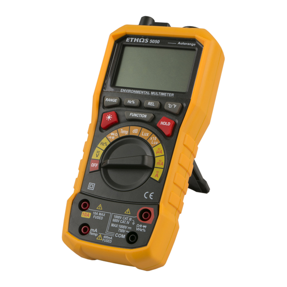
Overview The instrument is a hand-held intelligent multifunctional measurement instrument, integrating noise, illuminance, humidity, temperature and digital multimeter into one. With large LCD digital display (three sets of data display) and backlight, it’s easy for user to read, with overload protection and battery Low indication. Whether for professionals, factories, schools, amateurs or family, it’s an ideal multi-functional instrument. - Page 11 Diode test indicator Humidity unit AC voltage or current " Battery Low indicator Humidity display area indicator Relative value measurement Illuminance unit Data hold indicator indicator Resistance Automatic range indicator Auto power-off indicator frequency unit DC voltage or current indicator + Capacitance unit &...
-
Page 12: Buttons
Buttons RANGE: switch between automatic range and manual " range ¡ £ ¡ £ Hz%: switch between frequency and duty ratio REL: relative value measurement °C/°F: switch between centigrade and Fahrenheit & HOLD: data hold FUNCTION: switch among function selections : backlight... -
Page 13: Rotary Switch
Rotary Switch " AC or DC voltage, press FUNCTION button to switch Frequency, duty ratio, press Hz% button to switch Resistance, diode, connectivity, capacitance, press FUNCTION button to switch & Temperature measurement, press °C/°F button to switch unit Noise measurement Illuminance measurement Illuminance measurement x10 gear, measurement result=displayed value x10... -
Page 14: Input Socket
Input Socket Used for AC and DC current measurement (can measure maximum 10A), input socket for " frequency/duty ratio measurement (frequency measurement in current mode). Used for AC and DC microampere (µA) and milliampere (mA) measurement (can measure maximum 400mA) and input socket for frequency/duty ratio (frequency measurement in current mode); positive input socket of K type thermocouple temperature measurement. -
Page 15: At The Top
measurement. At the Top Illuminance induction area, when measuring the illuminance, this area " should be vertically aligned to the light source Normal temperature and humidity induction area Noise induction area, when measuring noise, this area should be aligned to the noise source Measurement Operation Manual and Automatic Range The instrument is equipped with manual and automatic range. - Page 16 2. Press button to increase the range, when reached the maximum range, the instrument will return to the minimum range. 3. Press and hold button for 2 seconds to quit manual range mode, the instrument displays “AUTO” symbol. Note: for function of frequency, duty ratio, capacitance, diode, connectivity, temperature, noise and illuminance measurement, the button is invalid.
-
Page 17: Measure Ac Voltage
measurement has no relative value measurement mode. Measure AC Voltage As shown in the figure on the right, set the instrument to the function of AC voltage measurement, contact the probe to the measured circuit, then read the display value. The ¡... -
Page 18: Measure Dc Voltage
Warning! Do not allow measurement of any voltage higher than DC 1000V or AC 750VRMS, otherwise it may cause instrument damage, electric shock or personal injuries. Do not allow applying voltage exceeding DC 1000V or AC 750V RMS between a public terminal and the earth, otherwise it may cause instrument damage, electric shock or personal injuries. -
Page 19: Measure Frequency And Duty
Note: Press Hz% button to measure the frequency and duty ratio of the AC voltage source, please refer to Measure Frequency. Warning! Do not allow measurement of any voltage higher than DC 1000V or AC 750VRMS, otherwise it may cause instrument damage, electric shock or personal injuries. -
Page 20: Measure Ac Or Dc Current
“COM”. 3. Contact the probe to the measured circuit, and measure the frequency. 4. Read the measurement result on the screen. Note: switch to Hz% shift and voltage or current shift to measure the frequency sensitivity and measurement range, please refer to Frequency accuracy index. Warning! Do not allow measurement of any voltage higher than DC 1000V or AC 750VRMS, otherwise it may cause instrument... - Page 21 as follows: 1. According to the actual current of measurement scroll the rotary knob to any shift among “ ”, “ ” and “ ”, press “FUNCTION” button and switch to AC or DC function. 2. According to the measured current, insert the red probe in “mA” socket or “10A” socket, and the black probe in “COM”...
-
Page 22: Measure Resistance
Caution To avoid any damage on the instrument or equipment, please check whether the fuse is damaged before measurement, and use correct input socket. Measure Resistance As shown in the figure on the right, set the instrument to the function of measurement, contact the probe to the measured circuit, then read the display value. -
Page 23: Measure Connectivity
Warning! Before measuring resistance, connectivity, capacitance or diode, please turn off the power supply and discharge all the high voltage capacitors, otherwise it may cause instrument damage, electric shock or personal injuries. Measure Connectivity As shown in the figure on the right, set the instrument to the function of measurement, contact the probe to the measured circuit, then read the display... -
Page 24: Measure Capacitance
Warning! Before measuring resistance, connectivity, capacitance or diode, please turn off the power supply and discharge all the high voltage capacitors, otherwise it may cause instrument damage, electric shock or personal injuries. Measure Capacitance As shown in the figure on the right, set the instrument to the function of measurement, contact the probe to the measured capacitor, then read the display value. -
Page 25: Measure Diode
Warning! Before measuring resistance, connectivity, capacitance or diode, please turn off the power supply and discharge all the high voltage capacitors, otherwise it may cause instrument damage, electric shock or personal injuries. Note: 1. In the circumstance that the input is open circuit, the instrument may display reading, press “REL”... - Page 26 to the function of measurement, contact the probe to the measured capacitor, then read the display value. The steps are as follows: 1. Scroll the rotary knob to “ ”, press “FUNCTION” button and switch to diode measurement function. 2. Insert the red probe in “ ”...
-
Page 27: Measure Temperature
Measure Temperature Measure normal temperature: The instrument is equipped with normal temperature measurement, only turn on the power supply of the instrument (all the shifts except OFF), it will display the temperature of current environment in normal temperature display area; to measure normal temperature you only need to place the instrument in the measurement environment. -
Page 28: Measure Humidity
Measure temperature by thermocouple: 1. Scroll the rotary knob to “TEMP”. 2. Insert the thermocouple into the input socket of the instrument, the positive end of the thermocouple (red color) into “mA” socket, and the negative end (black color) into “COM” socket. 3. -
Page 29: Measure Illuminance
shows current environment humidity in the humidity display area. Note: 1. Put the humidity sensor inside of the top end of the instrument. It takes longer time to achieve a balance with the measurement environment. So it has to be placed in the measurement environment for a longer time to obtain more accurate reading. -
Page 30: Auto Power-Off Function
2. Make the noise reception area at the top of the instrument face the sound source to be measured. 3. Read the measurement results on the screen. Note: Because strong wind (exceeding 10m/sec) will affect the microphone and lead to reading error, so when measuring in strong wind, please put a windshield in front of the microphone. -
Page 31: Data Hold
1. Press “ ” button and turn on the backlight. 2. Press “ ” button again and turn off the backlight; or after about 10 seconds the backlight will turn off automatically. Note: 1. The backlight source is LED, the working current is larger, although the instrument is equipped with a timing circuit (the timing time is about 10 seconds, that is, it will turn off automatically about 10seconds after the backlight is turned on), often using the backlight will shorten the battery life, so in unnecessary circumstances, the use of backlight source should be minimized. -
Page 32: General Technical Specifications
2. Press “HOLD” button again to clear the state of reading hold. General Technical Specifications l Environment condition of using: 600V CAT.IV and 1000V CAT.III Pollution level: 2 Altitude < 2000 m Working environment temperature and humidity: 0~40°C (<80% RH, <10°C non condensing) Storage environment temperature and humidity:-10~60°C (<70% RH, remove the battery) l... - Page 33 l Sampling rate: about 3 times/second. l Display: 4000 counter readout, temperature and humidity are displayed separately. Automatically display the unit symbols according to the shift of the measurement function. l Super range indication: it displays “OL”. l Low battery indication: when the battery voltage is lower than the normal working voltage, “ ”...
-
Page 34: Accuracy Specifications
Accuracy Specifications The accuracy applies within one year after the calibration. Reference condition: the environment temperature 18°C to 28°C, the relative humidity is no more than 80%, accuracy: ± (% reading + word). DC Voltage Input impedance:10MΩ Range Resolution Accuracy Overload protection: 1000V DC or 750V AC(RMS) Maximum input voltage:1000V DC 400mV... -
Page 35: Ac Voltage
400V 0.1V 1000V AC Voltage Input impedance: 10MΩ Range Resolution Accuracy Overload protection:1000V DC or 750V AC (RMS) 400mV 0.1mV Maximum input voltage:750V AC (RMS) 0.001V Frequency range: 50 ~ 60Hz; ±(0.8% reading+3) Note: 0.01V For small voltage range, if the probe doesn’t contact 400V 0.1V the circuit to be measured, it’s normal that there may be... -
Page 36: Ac Current
Maximum input current: mA socket: 400mA 40mA 0.01mA 10A socket: 10A 400mA 0.1mA 0.001A ±(2.0% reading +10) 0.01A AC Current Overload protection: µA、mA range: 400mA/1000V fuse Range Resolution Accuracy (ultra-speed fuse) 400µA 0.1µA 10A range: 10A/1000V fuse (ultra-speed 4000µA 1µA fuse) ±(1.5% reading +5) Maximum input current:mA socket: 400mA... -
Page 37: Connectivity Test
40kΩ 0.01kΩ 400kΩ 0.1kΩ 4MΩ 0.001MΩ 40MΩ 0.01MΩ ±(2.0% reading +5) Connectivity Test Range Function The resistance of the measured The open circuit voltage is about 0.5V circuit is less than 50Ω. The buzzer Overload protection:1000V DC or 750V AC (RMS) contained in the instrument will sound. -
Page 38: Frequency And Duty
40µF 0.01µF 100µF 0.1µF Frequency and Duty Resolut Through shift of Hz: Range Accuracy 1) Measurement range: 0 ~ 200kHz 2) Input voltage range: 0.5~10V AC (RMS) (the input voltage 9.999Hz 0.001Hz ±(2.0% reading+5) should be increased with the increase of the measured frequency) 99.99Hz 0.01Hz 3) Overload protection:1000V DC or 750V AC (RMS) -
Page 39: Diode Test
Compared with the range of measurement by using the “Hz” function of voltage and current shifts, using shift “Hz” to measure the frequency has larger range, however the measurement values exceeding the scope in above table are just for reference. Diode Test Range Resolution... -
Page 40: Humidity(Rh, Shown In Humidity Display Area
Humidity( RH, shown in humidity display area) Range Resolution Accuracy Working temperature: 0℃~40℃ Sampling period: about 20s 20 - 95% 0.1% ± 5.0%RH Temperature Normal temperature (temperature display area) Range Resolution Accuracy Sampling period: about 20s ℃ 0.1℃ 0℃ to 40℃ ±... -
Page 41: Maintenance
752℉~ ± 2.0% reading 1832℉ Maintenance General Regularly clean the outer cabinet with a damp cloth and mild detergent. Do not use abrasive or solvent. If there’s dust or wet in the input socket, the measurement may be affected. To clean the input socket: 1. - Page 42 l Only use exactly the same replacement parts to replace the blown fuse to prevent the hazard caused by the arc flash. l Please use the specified replacement fuse only. l The batteries contain dangerous chemicals which may cause burns or explosion. If exposed to chemical substances, please wash with water and go to a doctor in time for treatment.
Need help?
Do you have a question about the 5050 and is the answer not in the manual?
Questions and answers