Table of Contents
Advertisement
Quick Links
Advertisement
Table of Contents

Related Manuals for Grundig GSS HADA 5100 SPTS


Summary of Contents for Grundig GSS HADA 5100 SPTS
- Page 1 HADA 5100 SPTS...
-
Page 2: Table Of Contents
o n t e n t s 1 Safety regulations and notes ................3 2 General information ..................4 Packing contents ................4 Meaning of the symbols used ............... 4 Technical data..................4 Description ..................5 Software query .................. 6 3 Assembly ......................7 Installing the cassette ................7 EMC regulations ................ -
Page 3: Safety Regulations And Notes
a f e t y r e g u l a t i o n s a n d n o t e s • Assembly, installation and servicing should be carried out by authorised electricians. • Switch off the operating voltage of the system before beginning with assem- bly or service work or pull out the mains plug. -
Page 4: General Information
e n e r a l i n f o r m a t i o n 2.1 P aC k i n g C o n t e n t s 1 Cassette HADA 5100 SPTS 1 LAN cable 5 BNC cable 1 Brief assembly instructions 2.2 m... -
Page 5: Description
Connections LAN: ................1 RJ 45 socket ASI inputs: .............. 5 BNC sockets, 75 Ω Connection strip (10-pin): ....for supply voltages and control circuits RS 232 socket: ........serial interface for software update 2.4 d es C r i P t i o n The cassette converts five ASI input channels (ASI –... -
Page 6: Software Query
The cassette is controlled with the head-end station control unit. The LEDs for the LAN interface show whether a network connection exists and whether a data transfer is in progress. When the head-end station is switched on, the two-line LC display shows the software version of the control unit. -
Page 7: Assembly
s s e m b l y 3.1 i n s ta l l i n g t h e C a s s e t t e – Ensure the head-end station is mounted so it will not be able to vibrate. Avoid, for example, mounting the head-end station onto a lift shaft or any other wall or floor construction that vibrates in a similar way. -
Page 8: Emc Regulations
3.2 emC r e g u l at i o n s To comply with the current EMC regulations, it is necessary to connect the lines leading in and out of the head-end station using cable terminals. When mounting the cassette in a head-end station which is installed in a 19" cabinet, make sure the connections leading in and out for the 19" cabinet are made using cable terminals. The attenuation of shielding of the connection lines for ASI and antenna must meet the requirements for "Class A". CLASS • Insert the required number of cable terminals in the openings provided in the head-end station or in the 19" cabinet. Tighten the nuts on the cable terminals until the teeth on the lock washer have penetrated the exterior coating and a good connection is made between the hous- ing and cable terminals. -
Page 9: Cassette Overview
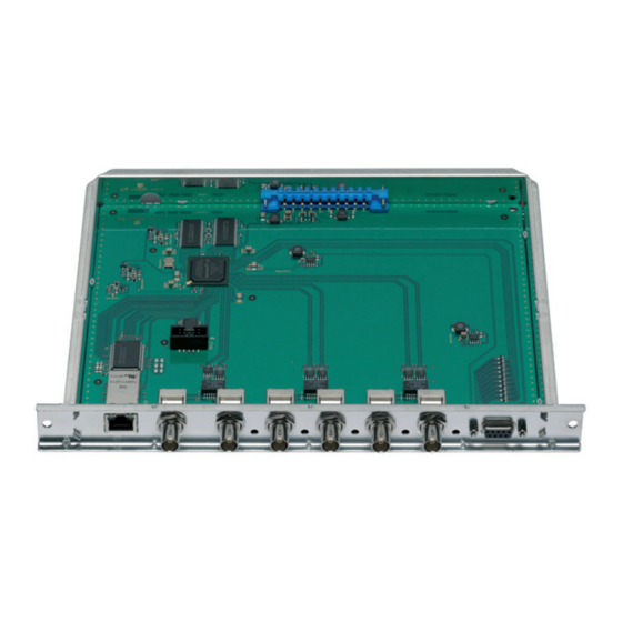
3.3 C a s s e t t e ov e rv i e w Status LED of the LAN interface (data transfer) LAN socket Status LED of the LAN interface (network connection) without function ASI input 5 Status LED ASI input 5 ASI input 4 Status LED ASI input 4 ASI input 3... -
Page 10: The Control Panel At A Glance
C o n t r o l P a n e l g l a n C e 4.1 m e n u i t e m s Programme the cassette using the buttons on the control unit of the head-end station. -
Page 11: Programming
r o g r a m m i n g 5.1 P ro g r a m m i n g Pro C e d u r e Ein / On BE–Remote V 45 please wait … t > 10 s Box 1 ……... - Page 12 ◀ ▶ Bx 4 INPUT ASI-1 IP-OUT ▶ ASI-1 OK => 227. auto 1 …5 INFO: – – –/OK on / off ◀ ▶ ASI-1 MODE / PORT UDP / RTP, 1234 0 … 65535 copy ◀ ▶ ASI-1 PKTS / FEC off / 10/9 …...
-
Page 13: Programming The Cassette
5.2 P r o g r a m m i n g t h e C a s s e t t e —> Pressing the button for longer than 2 seconds cancels the programming procedure. This takes you back to the program item "Selecting the cassette"... -
Page 14: Ethernet Parameters
• Press the button. —> The "Ethernet parameters" – "ETHERNET" main menu is activated. t h e r n e t Pa r a m e t e rs In this menu you specify whether the Ethernet parameters for the cassette are entered automatically by a connected server ("DHCP"), or whether you want to enter them manually ("stat"). -
Page 15: Address Range
• Use the buttons to place the cursor under the digit of the IP address displayed to be set and use to set the IP address wished. • Press the button. —> The "Address range" – "IP-MASK" sub menu is activated. d d r es s r a n g e In this menu you define the address range for the cassettes connected to the... -
Page 16: Udp Port
udP P o r t The UDP port setting is required if the cassette shall be controlled via remote access and the standard port 60000 can not be used. Bx 4 UDP-PORT 60000 • Use the buttons to place the cursor under the digit of the port number displayed to be set and use to set the port number wished ("0"... -
Page 17: Output Ip Addresse
iP u t P u t a d d r es s e In this menu you set the IP address for the ASI input signal selected. ASI-1 IP-OUT 227. —> Use an IP address of the multicast range (e.g. 227.40.50.x). •... -
Page 18: Quantity Of Data Packets
Selecting the transmission protocol • Press the button to position the cursor under "UDP". • Using the buttons to select the transmission protocol wished: —> "UDP" – The User Datagram Protocol is for the connectionless trans- mission of data without acknowledgement from the receiver. "RTP"... - Page 19 Defining the quantity of data packets • Using the buttons define the quantity of MPEG data packets in one IP data packet ("1" … "7"). —> Setting "7" results the smallest overhead. Setting the forward error correction • Press the button to position the cursor under "off"...
-
Page 20: Stuffing The Output Data Rate
t u f f i n g t h e o u t P u t data r at e In this menu it is to set, whether the current output data rate remains "unmodi- fied" or whether it is stuffed to a "constant" value. This value is a little bit higher than the current "maximum"... -
Page 21: Factory Reset
aC to ry r es e t In this menu you can reset all settings to the factory defaults. Bx 4 FACTORY Bx 4 FACTORY ▶ Defaults => STORE => M • Press the button. —> The submenu "FACTORY STORE" is invoked. —>... -
Page 22: Final Procedures
i n a l Pro C e d u res After installing the head-end station, upgrading accessories or installing cas- settes it is necessary to tighten all cable connections, cable terminals and cover screws in order to maintain compliance with current EMC regulations securely. • Securely tighten the cable bolted connections using an appropriate open- ended spanner. • Mount the front cover (see assembly instructions of the head-end station). - 22 - HADA 5100 SPTS... - Page 23 Declaration of CE conformity GSS Grundig Systems GmbH • Beuthener Straße 43 • D-90471 Nuremberg Phone: +49 (0) 911 / 703 8877 • Fax: +49 (0) 911 / 703 9210 www.gss.de/en • info@gss.de CLASS CLASS Service: Phone: +49 (0) 911/703 2221; Fax: +49 (0) 911/703 2326; service@gss.de Alterations reserved.
Need help?
Do you have a question about the GSS HADA 5100 SPTS and is the answer not in the manual?
Questions and answers