Table of Contents
Advertisement
Quick Links
Advertisement
Table of Contents

Related Manuals for Grundig GSS SID 162 A


Summary of Contents for Grundig GSS SID 162 A
- Page 1 SID 162 A...
-
Page 2: Table Of Contents
o n t e n t s 1 Safety regulations ....................3 2 General information ..................4 Scope of delivery ................4 Meaning of the symbols used ............... 4 Technical data..................4 Description ..................5 3 Overview ......................6 4 Installing the SAT IF input distributor ..............7 5 Connecting the SAT IF input distributor ..............8 Connecting the RF connections ............. -
Page 3: Safety Regulations
a f e t y r e g u l a t i o n s • The standards IEC/EN/DIN EN 50083 resp. IEC/EN/DIN EN 60728 must be observed. • Do not perform installation and service work during thunderstorms. • Assembly, installation and servicing should be carried out by authorised electricians. -
Page 4: General Information
e n e r a l i n f o r m a t i o n 2.1 s C o p e d e l i v e ry 1 SAT IF input distributor SID 162 A 8 SAT cables 1 Brief Assembly Instructions Mounting material 2.2 m... -
Page 5: Description
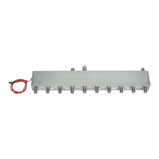
2.4 d es C r i p t i o n The SAT IF distributor SID 162 A is equipped with two SAT IF inputs, one loop- through output and 10 SAT IF outputs. This enables to distribute two reception areas to 4 and 6 SAT IF outputs. -
Page 6: Overview
v e r v i e w 0 dB 2…4 dB 1…3 dB LNB power connection Input 1 Input 2 Outputs of input 1 Loop-through output of Outputs of input 2 input 1 with terminator - 6 - SID 162 A... -
Page 7: Installing The Sat If Input Distributor
sat if n s t a l l i n g t h e i n p u t d i s t r i b u t o r Before installing or changing a module or accessory, switch off the head-end station or unplug the power cable from the mains power socket. Installing the SAT IF input distributor take care that no cables are squeezed off or injured. • Remove the front cover – and if present – the bottom plate of the head-end station. -
Page 8: Connecting The Sat If Input Distributor
sat if o n n eC ti n g th e i n pu t d is tr i buto r 5.1 C rf o n n e C t i n g t h e C o n n e C t i o n s •... -
Page 9: Lnb Power Supply
5.3 lnb p ow e r u p p ly The possible maximum power consumption of the LNB is derived from the maximum available current provided by the head-end stations LNB port, less about 100 mA for the operation of the input distributor. Dependent on the head-end station the LNB voltage is 18 V or 12 V. -
Page 10: Final Procedures
i n a l pro C e d u res After installing the head-end station, retrofitting accessories or installing mod- ules it is necessary to tighten all cable connections, F terminals and cover screws in order to maintain compliance with current EMC regulations and to ensure a reliable operation. • Securely tighten the cable connections (F connector) using an open-ended spanner (spanner gap 11 mm). • Mount the front cover and - if there is one - the base plate (see assembly instructions of the head-end station). - Page 11 CE - Declaration of Conformity GSS Grundig Systems GmbH • Beuthener Straße 43 • D-90471 Nuremberg Phone: +49 (0) 911 / 703 8877 • Fax: +49 (0) 911 / 703 9210 www.gss.de/en • info@gss.de Service: Phone: +49 (0) 911/703 2221; Fax: +49 (0) 911/703 2326; service@gss.de Alterations reserved.
Need help?
Do you have a question about the GSS SID 162 A and is the answer not in the manual?
Questions and answers