Table of Contents
Advertisement
Quick Links
Advertisement
Table of Contents

Related Manuals for Grundig GSS SID 162


Summary of Contents for Grundig GSS SID 162
- Page 1 SID 162...
-
Page 2: Table Of Contents
o n t e n t s 1 Safety regulations ....................3 2 General information ..................3 Scope of delivery ................3 Meaning of the symbols used ............... 4 Technical data..................4 Description ..................4 3 Overview ......................5 4 Installing the SAT IF input distributor ..............6 5 Connecting the SAT IF input distributor ..............7 Connecting the HF connections ............ -
Page 3: Safety Regulations
a f e t y r e g u l a t i o n s • The standards IEC/EN/DIN EN 50083 resp. IEC/EN/DIN EN 60728 must be observed. • Do not perform installation and service work during thunderstorms. • Assembly, installation and servicing should be carried out by authorised electricians. -
Page 4: Meaning Of The Symbols Used
2.2 m e a n i n g t h e s ym b o l s u s e d Important note • Performing works 2.3 t e C h n i C a l data The requirements of the following are met: 2011/65/EU, 2014/30/EU, 2014/35/EU The product fulfils the guidelines and standards for CE labelling (page 10). -
Page 5: Overview
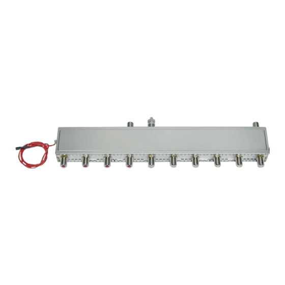
If the loop-through output is not used it must be terminated using the terminator supplied. The DC power feed (max. 800 mA ) is used for the power supply of the LNBs connected. The SAT IF distributor SID 162 is designed exclusively for use in the head-end station. -
Page 6: Installing The Sat If Input Distributor
sat if n s t a l l i n g t h e i n p u t d i s t r i b u t o r Before installing or changing a module or accessory, switch off the head- end station or unplug the power cable from the mains power socket. Installing the SAT IF input distributor take care that no cables are squeezed off or injured. • Remove the front cover and the base plate of the head-end station. •... -
Page 7: Connecting The Sat If Input Distributor
sat if o n n eC ti n g th e i n pu t d is tr i buto r 5.1 C hf o n n e C t i n g t h e C o n n e C t i o n s •... -
Page 8: Connecting The Power Supply
5.2 C o n n e C t i n g t h e p ow e r s u p p ly • Connect plug of the cable of the LNB power connection to one of the contacts “LNB power supply” (800 mA total). -
Page 9: Final Procedures
i n a l pro C e d u res After installing the head-end station, retrofitting accessories or installing mod- ules it is necessary to tighten all cable connections, F terminals and cover screws in order to maintain compliance with current EMC regulations and to ensure a reliable operation. • Securely tighten the cable connections (F connector) using an open-ended spanner (spanner gap 11 mm). • Programme the modules connected and the head-end station if necessary. • Position the breakthroughs in the base plate above the fastening screws •... - Page 10 CE - Declaration of Conformity GSS Grundig Systems GmbH • Beuthener Straße 43 • D-90471 Nuremberg Phone: +49 (0) 911 / 703 8877 • Fax: +49 (0) 911 / 703 9210 www.gss.de/en • info@gss.de Service: Phone: +49 (0) 911/703 2221; Fax: +49 (0) 911/703 2326; service@gss.de Alterations reserved.
Need help?
Do you have a question about the GSS SID 162 and is the answer not in the manual?
Questions and answers