
Subscribe to Our Youtube Channel
Related Manuals for LiteGait 300 Series


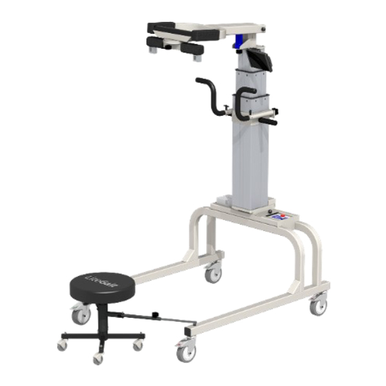
Summary of Contents for LiteGait 300 Series
- Page 1 Operator & Service Manual 300 Series 300P Series 300 Standard 300 Deluxe 300P Standard 300P Deluxe 400 Series 400 Standard 400 Deluxe 400 Deluxe Tall 500 Series 500 Standard 500 Deluxe Tall 500 Deluxe 300 / 400 / 500 Series...
- Page 3 Serial Number of Your Device: Note: Please keep your serial number in a safe and secure location. The serial number must be provided when seeking service for your LiteGait® device. The serial number provides us access to technical informa- tion regarding your device.
- Page 5 IMPORTANT SAFETY INSTRUCTIONS ***WARNING*** READ ALL INSTRUCTIONS BEFORE USING LiteGait® Maximum Unit Height Maximum Patient Weight LiteGait® 300 Standard 7’ 11” 300 lbs LiteGait® 300 Deluxe 7’ 11” 300 lbs LiteGait® 300P Standard 7’ 6” 300 lbs LiteGait® 300P Deluxe 7’...
- Page 7 If you have questions about the possible uses of LiteGait® with particular patients, or are in need of some ideas for ways to use LiteGait® more effectively, please do not hesitate to contact us for information relating to your individual situation. Our website also offers valuable information.
-
Page 9: Table Of Contents
About Your Unit ......................16 USING Your LiteGait® ....................17 I. Control Unit ......................17 II. Charging LiteGait® ....................17 III. Charging LiteGait® I 300 Standard/Deluxe ............17 IV How to Adjust Yoke Height ................... 18 V. FlexAble ....................... 18 VI. FreeDome ......................18 V. -
Page 10: Litegait® 300Assembly
LiteGait® I Assembly Instructions: Read below & follow pictures. NOTE: Two people are required for safe assembly. NOTE: Your LiteGait® may look different than the following images. NOTE: If you have any questions during installation, please 5.) Carefully cut all black contact Mobility Research Service Dept. - Page 11 11.) Before attaching the post 12.) Lower handlebars on to the base, the LiteGait® actuator and tighten knobs Yoke yoke and legs should be before lifting. oriented in the same direction as shown in the picture to the right.
- Page 12 Tighten the bolts until snug using the Allen wrench. 24.) Carefully remove all shrink wrap from LiteGait®. 15.) Tighten the bolts until snug using the Allen wrench. CAUTION: DO NOT over Contact Mobility Research at 1-800-332-9255 Option 1 For tighten the bolts.
- Page 13 LiteGait® I Assembly Instructions: Read below & follow pictures. NOTE: Two people are required for safe assembly. NOTE: Your LiteGait® may look different than the following images. NOTE: If you have any questions during installation, please 5.) Carefully cut all black contact Mobility Research Service Dept.
- Page 14 11.) Before attaching the post 12.) Lower handlebars on to the base, the LiteGait® actuator and tighten knobs Yoke yoke and legs should be before lifting. oriented in the same direction as shown in the picture to the right.
- Page 15 22.) LiteGait® is powered by 15.) Insert bolts and hand a rechargeable battery. To tighten. Make sure while one charge remove battery from person is inserting bolts, the base and connect charger to other is holding the actuator. battery. Tighten the bolts until snug using the Allen wrench.
-
Page 16: Litegait® Diagram
12. FreeDome Yoke - Removable (OPTIONAL) 13. Integrated FreeDome Yoke (OPTIONAL) 14. Gaiter Stool (OPTIONAL) NOTE: Your LiteGait® may look different than image above HANDLEBARS: Unit has two adjustable handlebars. The About Your LiteGait® handlebars are attached to the unit using two knobs. NOTE: Over tightening the knobs may cause damage. -
Page 17: Using Your Litegait
The emergency ON/OFF Button is the ON/OFF switch Red LED indicates 3. After charging battery for the LiteGait. To turn the device on, rotate the red battery is charging. Green for 6-8 hours or overnight, button clockwise and it should pop outward. To turn... -
Page 18: How To Adjust Yoke Height
IV. How to Adjust Yoke Height FlexAble allows for the rigid yoke to become position The LiteGait® powered actuator column is raised and flexible, with up to 5 inches of travel. Thus, you can lowered by a hand switch with two up and two down maintain the rigid yoke position or make it flexible giving arrows. -
Page 19: Adjusting Handlebars
Once aligned this locks the swivel of the casters and is beneficial for walking in a straight path or placing LiteGait® over a treadmill. Once the unit is positioned over a treadmill, all four caster brakes need to be locked Directional Locking Casters with Treadmill Position LiteGait®... -
Page 20: Harness Application
There are four buckles on the top and bottom of the harness wrap. The four top buckles extend beyond the harness from the top seam and attach to the LiteGait® overhead straps. The bottom four buckles attach to the groin piece and do not extend past the bottom seam of the harness. - Page 21 Using Your LiteGait® Harness Application - While Standing 1. Wrap harness around patient with lowest side straps even with greater trochanter. 2. Connect buckles top to bottom. 3. Adjust side straps* to the patient from bottom to top, alternate sides and tighten evenly.
- Page 22 Using Your LiteGait® Harness Application – In Supine 1. Roll patient away from you. 2. Attach groin piece and place harness on patient with half of the harness rolled and Figure 1 under patient. (Figure 1) 3. Hold harness in place with lowest strap at greater trochanter 4.
- Page 23 Leave a few inches of slack in the front straps. 3. Once the patient is connected, unlock casters. With one hand on LiteGait, press up button on hand switch to lift patient into a standing position. Roll LiteGait® forward slightly while lifting so patient ends up directly under the yoke buckles.
- Page 24 Stepping up onto Treadmill (Continued) 7. To exit the unit, reverse the process. Keep directional casters locked until the LiteGait® is at the end of the treadmill. It is helpful to ensure that the locking casters are nudged into an outward rolling position so they do not get caught on the treadmill as they roll.
-
Page 25: Unit Care And Maintenance
Unit Care and Maintenance LiteGait® Maintenance Your LiteGait® has been specially designed to be durable and relatively maintenance free. The frame is constructed from high strength steel, and has been painted with a special powder coat to resist rust and scratches. - Page 26 To maintain the highest quality of function and safety, it is extremely important that you conduct regular maintenance checks of your LiteGait® unit and all of its parts. Please refer to the following checklist for an inspection guideline. If you should have any questions concerning the functional status of any of the LiteGait® parts, please contact the Service &...
- Page 27 When unlocked the casters should swivel and rotate freely. Your LiteGait® may differ from the image shown above. Below are images of the LiteGait® harness showing signs of wear that would indicate replacement. Wear On Buckle Straps Loose Stitching...
-
Page 28: Troubleshooting
The Directional Locking Casters are labeled with a green STEER sticker and engage misaligned when the caster is aligned with the leg of the base. If the LiteGait® does not move forward and backward when the directional locking casters are locked they are not aligned properly. - Page 29 Troubleshooting LiteGait® Troubleshooting - Harness Symptom: Patient is complaining of groin or harness discomfort. Possible Cause: Resolution: The harness wrap and/or the groin piece are The harness and groin piece should be securely tightened from the start. The not tight enough.
-
Page 30: Parts List
The female end connects into the buckles on the harness. Provides adjustable length and elastic hand-free Q-Straps PHQST pelvic cueing/support while using LiteGait To place a part order, please visit LiteGait.com/service or email Service@LiteGait.com www.LiteGait.com 1-800-332-9255... - Page 31 Rectangular metal plate to cover the cables to the control box. PS35E-H LiteGait® I Parts List – Power System 300P / 400 / 500 Series - Power System A split red and green color coded connection cord that electrically Actuator Cord PS50E-A connects the control box to the actuator.
- Page 32 Directional Locking Caster B50G34L-D labeled with a green STEER sticker. Includes Low Profile Hardware LiteGait® I Parts List Base - 300P / 400 / 500 Series 5” Wheel with hardware that locks via a tab labeled with a red Total Locking Casters B50G34L-C BRAKE sticker.
-
Page 33: Appendix A. Freedome
LiteGait®. 1. Introduction to FreeDome FreeDome is an accessory for the LiteGait® that enables users to experience the freedom of 360 degrees rotation while fully supported by LiteGait®. 2. FreeDome Components 1. - Page 34 LiteGait® 6. Securing FreeDome Rotate the (8) Top Latch until positioned parallel to the arms of the LiteGait® yoke, to secure the FreeDome to the LiteGait®. Rotate the Top Latch Parallel to LiteGait® Yoke Arms www.LiteGait.com...
- Page 35 The FreeDome can be easily removed by reversing the installation directions. As with attaching the FreeDome, validate that the pivot bar is oriented parallel with the arms of the LiteGait® Yoke. Rotate the (8) Top Latch until perpendicular with the yoke arms and pull downward on the (7) Yoke Alignment Lip.
-
Page 36: Appendix B. Bisym
BiSym also allows for measuring in the side stepping position. Side stepping measurement s are displayed as total weight only. DISPLAY UNITS ® Display the values of suppor t provided by the LiteGait in the Weight selected weight unit s or a percentage of the patients body weight. - Page 37 “Bearing” Limit support from, ® LiteGait , select “Support” If a weight goal is set, adjusting the patient weight will cause the percentage goal to adjust. If a percentage goal is set, adjusting patient weight will cause weight goal to adjust.
- Page 38 Positive results being will produce positive “chimes” noises PATIENT FEEDBACK - Use with the Integrated FreeDome Yoke Note when using the SIDE orient ation, the measurement is limit ed to the total measurement. Left and Right readings are disabled. www.LiteGait.com 1-800-332-9255...
- Page 39 Wi-Fi network. Print Session using printer connected to tablet, Wi-Fi or Wi-Fi Saving the session will direct. save a copy of the report and data file on the tablet under the BiSym folder. SECTION INTENTIONALLY LEFT BLANK www.LiteGait.com 1-800-332-9255...
- Page 40 3.Inser t edge of tablet into inst ruct ions to install tablet holder while sliding holder while sliding holder to LiteGait. opposite edge of holder opposite edge of holder CHARGING BISYM BATTERY / DISPLAY D i s c o n n e c t t h e 2.
- Page 41 7. Touch the menu at the t o p r i g h t , s e l e c t 10. Select configuration. the Bisym device 8. Enter password “mobilit y” to open 11. Select Apply the configuration screen www.LiteGait.com 1-800-332-9255...
- Page 42 The password access the configuration screen is “mobility”. Press OK to access configuration. ZERO CALIBRATION: ® Connect harness to LiteGait MOBILITY without any additional weight. RESEARCH Press Zero to set zero calibration USE ONLY. Select BiSym Units Press apply to Side View box should be selected save and exit..
-
Page 43: Resource Directory
Service@LiteGait.com Clinical Support ClinicalSupport@LiteGait.com Education Department Education@LiteGait.com Sales@LiteGait.com Sales Department POSTAL ADDRESS: Mobility Research P.O. Box 3141 Tempe, AZ 85280 LiteGait® is a Registered Trademark of Mobility Research, Inc. PO Box 3141, Tempe AZ, USA 85280. (2017 US) www.LiteGait.com 1-800-332-9255...
Need help?
Do you have a question about the 300 Series and is the answer not in the manual?
Questions and answers