Table of Contents
Advertisement
Quick Links
Advertisement
Table of Contents

Subscribe to Our Youtube Channel
Related Manuals for Lennox EMEA Euromon 100 Series


Summary of Contents for Lennox EMEA Euromon 100 Series
- Page 1 INSTALLATION, USER AND MAINTENANCE MANUAL Refrigeration monoblock EUROMON 01.2020...
-
Page 3: Table Of Contents
INDEX 1. PRODUCT SPECIFICATIONS ..........................3 1.1. DESCRIPTION..............................3 1.2. DESIGNATION..............................4 1.3. OPERATING LIMITS.............................4 1.4. TECHNICAL CHARACTERISTICS AND DIMENSIONS ..................4 1.5. EQUIPMENT DESIGN ............................5 2. UNIT PREPARATION FOR USE..........................5 2.1. TRANSPORT ................................5 2.2. IMPORTANT SAFETY WARNINGS........................6 2.3. INDICATIONS ...............................7 2.4. INSTALLING THE UNIT............................9 2.5. -
Page 4: Product Specifications
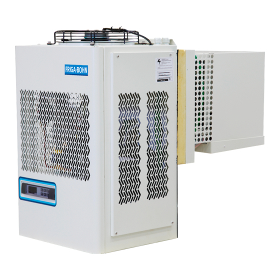
1. PRODUCT SPECIFICATIONS 1.1. DESCRIPTION EUROMON commercial equipments are compact wall compression cooling units, air-cooled, for cold storage rooms which have a small volume and for use in medium and low temperature, governed by an intelligent control. The power supply is single phase or three phase depending on the equipment. -
Page 5: Designation
1.2. DESIGNATION EMB 2 009 M 1 Z Indicates the unit family Indicates a group within the family Indicates the compressor Indicates the work range: M = refrigeration (medium temperature) L = freezing Indicates the voltage 1= 230/1/50 2= 220/1/60 3 = 230/3/50 4 = 220/3/60 5 = 400/3/50... -
Page 6: Equipment Design
CORTE PANEL – PANNEL CUT – COUPÉ PANNEAU EQUIPO – UNIT - UNITÉ TAMPON – PLUG IN – series SUR PANNEAU HORIZONTAL VERTICAL 1000 1050 1.5. EQUIPMENT DESIGN The units are agree with the those directives: • Machine security.…………………………… 2006/42/CE •... -
Page 7: Important Safety Warnings
WARNINGS Ensure no people are transiting through the area in which the machine is being transported and handled. RISK OF KNOCKS, TRAPPING AND CRUSHING. Whether the unit is packaged or not, it must always be transported, hoisted and handled in its original position, never laid down, for safety reasons and to prevent it from falling. -
Page 8: Indications
CAUTION This unit is not designed to work in an explosive atmosphere. Its use in a potentially explosive environment is therefore strictly forbidden. CAUTION This unit is not designed to work in a saline atmosphere. In this case the condenser and/or evaporator will need to be protected using the most suitable systems. -
Page 10: Installing The Unit
2.4. INSTALLING THE UNIT To guarantee correct functioning of the EUROMON, for optimising its electrical consumption per Kg of product stored and to prevent breakdown, it is vitally important that it is placed in a suitable location and properly used. Condenser - Ensure air is circulating through the condenser - Locate it away from sources of heat... - Page 11 For equipments with centrifugal fan in the condenser, you must install a duct with the following measures for each unit. In any case the length of this duct must not exceed 10m. Diámetro del conducto Duct diameter series Diamètre conduit...
-
Page 12: Protective Devices And Safety Measures
2.7. PROTECTIVE DEVICES AND SAFETY MEASURES The manufacturer has provided the following safety protections: 1. The metal casing is bolted to the structure. 2. The fans are bolted to the metal structure. 3. The fan access is covered by a grille bolted in place. 4. -
Page 13: Adjustment And Control
CAUTION The line connection must be made with a suitable protection device (magnetothermic switch or magnetothermic differential switch) selected by the installer or by qualified, authorised staff on the basis of the line type and consumption indicated on the unit label. If there is more than one unit in a cold room, each unit must have its own protection device. -
Page 14: Cold Room Light
To protect the compressor from successive start-up and stopping, the adjustment system includes an anti- short cycle timer. The unit automatically goes into defrost mode after a cooling cycle functioning time of 4 hours. The unit is supplied with the defrost mode controlled by the internal battery temperature. In this mode, the defrosting process ends when the internal battery reaches a temperature of 10ºC, or after 25 minutes have elapsed. -
Page 15: Control Functions
For viewing the minimum temperature set. In programming mode it enables the parameter list to be browsed or the value displayed to be reduced. If this button is pressed and held down for 3 seconds, the defrost cycle begins. For switching the cold room light on or off. For switching the unit on or off. -
Page 16: Indicator Lights
3. press the buttons to change the value. 4. press set to record the new value and go on to the next parameter. 5. to exit, press set and the button or wait for 15 seconds. • To block the keypad.- 1. -
Page 17: Pal/Ca Alarm
The sensor failure alarms “P1”, “P2” and “P3” switch off 10 seconds after the failure has been rectified. The cold chamber temperature alarms “HA” and “LA” switch off when the normal values are reached again or when defrosting begins. The door alarm “dA” switches off when the door is closed. The alarm “CA”... - Page 18 Evaporator fan does not work. Analyze fan output on the microprocessor 4-0. In the display, under the fan symbol, the red dot must be fixed so that the fan output is activated, this will happen when pb2 reads 2ºC below the FST value, that is, if the origin parameters have not been manipulated at 6ºC in the low equipment and 8ºC in the media equipment.
-
Page 19: P1, P2, P3, P4 Alarm
RELE Amarillo Ok SALIDA Y TEMPORIZACION LED FALLO SOBRETENSION U> AJUSTE LIMITE SOBRETENSION LED FALLO SUBTENSION U< AJUSTE LIMITE SUBTENSION AJUSTE RETARDO FUNCION U> U< L E D A M A R I L L O L E D R O J O L E D R O J O E R R O R CONFIGURACION... -
Page 20: Da Alarm
Rest of alarm probes; perform the same analysis to determine cause. 3.12. dA ALARM Indicative of analogue input micro door open. Possible causes: 1 Analogue input terminals 19-13, must be closed, check ferrules and connection, possible bad contact. 2The micro door cable bridge has been cut. The cable for micro door supplied to be bridged, ie connected to each other. -
Page 21: Parameter List
3.14. PARAMETER LIST Code Description Cool. Freez. Temperature setting 2 ºC -18 ºC Indicates the difference with respect to the temperature setting above which the compressor will start up Thermostat probe calibration (1) Probe 2 presence (the probe is connected) Indicates the time of the anti-short cycle in minutes, the minimum time interval between the 3 min... -
Page 22: Starting Up The Unit
3.16. STARTING UP THE UNIT Before starting up the cooling unit, the following operations must be performed: Plug the unit into the mains. The display will switch on and the word OFF will appear. If warm-up of the unit is required, it must remain in this state for at least three hours. If the unit has a voltage monitor incorporated, it must remain turned to OFF for at least 7 minutes, so that the monitor can run the calculation phase. -
Page 23: Periodic And Preventive Maintenance
the environment where said unit has been installed). This operation must be carried out with the equipment stopped: it is advisable to use a jet of air from the outside to the inside. When this is not possible, use a long bristle brush from the outside of the condenser. - Page 24 - The space the unit is located in is not sufficiently ventilated. - There are anomalies in the electrical supply network. - The condenser fan is not functioning properly. This protective device goes back to its original position automatically. 2. Ice formation in the evaporator (preventing correct air flow). This can be caused by: - The door being opened too far, or being left open for too long.
-
Page 25: Failure Analysis
4.6. FAILURE ANALYSIS Symptom Cause Solution Very high a) Excess load a) Collect refrigerant evaporator b) High cold room temperature b) Check for overheating pressure with c)Compressor air intake not c)Check the state of the compressor and respect to air correctly sealed replace it input. -
Page 26: How To Order Spare Parts
4.7. HOW TO ORDER SPARE PARTS If you need to order any spares, please state the serial number figuring on the unit label. WARNING Components must only be replaced by authorised, qualified staff. 4.8. SCRAPPING THE UNIT If the unit is to be scrapped, its components must not be abandoned in the environment; they must be disposed of through companies authorised to collect and recycle special waste, in accordance with the laws applicable in the country in which the unit is used. - Page 28 LENNOX EMEA se réserve le droit d'apporter toute modification sans préavis. LENNOX EMEA reserves itself the right to make changes at any time without preliminary notice. LENNOX EMEA Angaben und Abbildungen unverbindlich. Änderungen vorbehalten. LENNOX EMEA se reserva el derecho de aportar cualquier modificación sin preaviso.
Need help?
Do you have a question about the Euromon 100 Series and is the answer not in the manual?
Questions and answers