
Related Manuals for RedEarth DropBear


Summary of Contents for RedEarth DropBear
- Page 1 DropBear_Installation Manual DropBear Battery Energy Storage System - On or Off-Grid - (Single Phase) Installation Manual RE_PROD_0011 Version #2 Page 1 of 20 Issue Date 28/07/2020...
- Page 2 DropBear_Installation Manual RedEarth Energy Storage Ltd 15 Fienta Place Darra – QLD 4076 Australia Tel: +61 7 3279 6707 Email: info@redearth.energy Web: www.redearth.energy RE_PROD_0011 Version #2 Page 2 of 20 Issue Date 28/07/2020...
-
Page 3: Safety Procedures
The DropBear must only be installed by suitably qualified personnel. Many of the procedures covered in the INSTALLATION sections of this manual have inherent risks. Whilst the DropBear is designed to be safe, including residual current device and double insulated cables, the voltages connected or generated by the equipment are hazardous and potentially fatal. - Page 4 PV Solar array and generator with either auto or manual start. The DropBear is designed to be installed indoors or outside in a shaded and weather protected environment against a wall. A changeover switch is included in case of system failure. In this case the loads can then be run off a generator until the system is operational again.
-
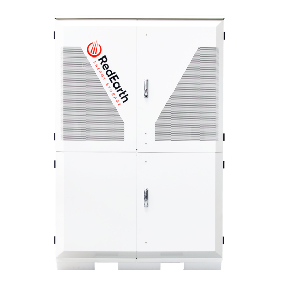
Page 5: Physical Specifications
DropBear_Installation Manual Physical Specifications DropBear Weight: 205kg without any Lithium batteries (42kg per battery) Dimensions: 200.5 cm H x 131.4 cm W x 65.6 cm D DropBear Minimum Clearance Dimensions: 210 cm H x 166.7 cm W x 117.4 cm D... - Page 6 Components Inside: The DropBear has two main areas, one for the batteries and the other for the switches and electronic equipment. Each section has a key-lockable double door. The top enclosure contains all of the electric-electronic equipment, switches and AC connection terminals.
- Page 7 Because of lithium batteries properties, it is possible to install additional batteries in your system at any time, please contact RedEarth for further details. RE_PROD_0011 Version #2...
- Page 8 Components Attached to the top of this chamber there are two fully enclosed battery busbars with the correct number of battery cables. The DropBear comes fully equipped with the following items. • DropBear pre-wired enclosure • Selectronic inverter • Fronius Primo inverter •...
-
Page 9: Installation
Each battery module weighs 42kg and up to 12 can be installed in the system. The DropBear is designed to be placed against a wall in a shaded and weather protected area with the system securely connected to the wall with the wall bracket included. - Page 10 (or forklift) lifting it high enough to clear the bracket and slide in behind it. On the base of the DropBear, there is a hole at the front on each side. These holes are for securing the base with supplied Dyna-bolts, then plug these holes with supplied 25mm plugs to limit pest ingress.
- Page 11 DropBear_Installation Manual Installation Step 2: Electrically connect the DropBear NOTE: Before proceeding any further, ensure that all breakers and isolators, as well as those supplying power to the unit, are turned OFF. AC Connections All AC cables should be brought through the 25mm or 32mm holes on the left hand side of the rear panel (behind battery breaker), secured with a gland (or plain-to-screwed adaptor if using corrugated conduit), and attached to the correct terminals of the breaker as shown below.
- Page 12 DropBear_Installation Manual Installation Generator Auto-Start and Charger The DropBear contains four terminals in the Comms area. These terminals are displayed in the picture on the next page and can be identified as: • Gen Start: Dry-contact The two terminals on the left must be connected to a cable to activate the generator auto-start.
- Page 13 DropBear_Installation Manual Installation DC Connections Battery The batteries are located in the lower enclosure, behind the bottom double doors. If supplied separately, unbox the batteries, place them on the battery shelf, re-install the front battery rail and finally attach the battery cables. PV Connections The PV cables should be brought through the 25mm holes on the right-hand side of the unit using the supplied plain to screwed adapters.
- Page 14 Monitoring Connection The Dropbear uses a SwitchDin Utility Droplet Controller to provide remote monitoring for the system. The Utility Droplet Controller is a high-end but simple device that will allow RedEarth to monitor and provide accurate information on the system operation.
- Page 15 DropBear_Installation Manual Commissioning The DropBear is commissioned and tested in factory to guarantee correct operation. However, some last-minute parameter adjustments may be required (eg. generator size or warm-up time). Carefully follow the procedure below on how to make these alterations without compromising the existing configuration.
- Page 16 DropBear_Installation Manual Commissioning Step #3 Click on the “Connection” tab and then on “Connect”. The program will request you to “Save Site” before proceeding. Fill in a site name and then click “Save Site”. RE_PROD_0011 Version #2 Page 16 of 20 Issue Date 28/07/2020...
- Page 17 “Configure SP PRO” button to send the new settings back to the SP Pro. NOTE: In case of a factory reset on the parameters, the installer may contact RedEarth Energy Storage and by providing the DropBear’s serial number request the configuration file.
-
Page 18: Start-Up / Shutdown Procedure
DropBear_Installation Manual Start-up / Shutdown Procedure Once the DropBear is in place and correctly installed, you may start the system. To power up the unit you must follow the steps below: 1. Turn on individual battery breakers. This will charge up the capacitors inside the inverters. The LED on the inverter will flash and beep. - Page 19 Phone Tech support on +61 487 002 451 or +61 7 3279 6707. RedEarth also provides training in our facility in Brisbane. Training can potentially be arranged at your facilities if requested.
- Page 20 DropBear_Installation Manual Single Line Diagram (SLD) RE_PROD_0011 Version #2 Page 20 of 20 Issue Date 28/07/2020...
Need help?
Do you have a question about the DropBear and is the answer not in the manual?
Questions and answers