Advertisement
Advertisement
Table of Contents

Related Manuals for Studiomaster Professional AQUA Series

Summary of Contents for Studiomaster Professional AQUA Series
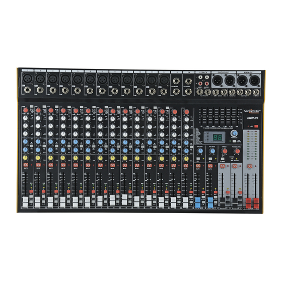
- Page 1 AQUA SERIES AQUA 14 AQUA 10 AQUA 8 1. Introduction 2. Features at a Glance 3. Input Section 4. Output Section 5. Effects Section 6. Mixer Set up 7. Block Diagram 8. Technical Specifications 9. Notes...
-
Page 2: Explanation Of Graphical Symbols
Explanation of Graphical Symbols CAUTION The lightning flash with arrowhead symbol within an equilateral triangle is intended to alert the RISK OF ELECTRIC SHOCK user to the presence of uninsulated “dangerous DO NOT OPEN voltage” within the product’s enclosure that may be of sufficient magnitude to constitute a risk of electric shock to persons. -
Page 3: Features At A Glance
5. EQ Section: The Aqua Series Mixer has a 3 Band Equalizer on both Mic & Stereo channels. The EQ is designed to be easy yet effective to use. It can be used to cut or boost certain frequencies to achieve a particular tone, or to eliminate any unpleasant characteristics. - Page 4 11. Signal LED: Indicates the incoming signal. This led glows when the Pre fade signal reaches to -20dB. 12. PFL Switch: When pressed t his sends signal from input channel to the headphone as well as bargraph. As this signal is pre fader it is possible to listen to the signal or monitor on bargraph with fader fully down before it is routed to main or group output.
-
Page 5: Output Section
16. Stereo Input Jacks: These TRS Jack Inputs are used to connect sources such as keyboards, drum machines, synthesizers, tape machines or returns from processing units. The inputs are BALANCED for low noise high quality sound. Avoid using UNBALANCED sources to prevent ‘hum’ being introduced into the sound system. Mono sources may be plugged into the left jack only. 17. - Page 6 41. Level: The LED level meter on the effects module displays the level fed to the effects processor. Take care to ensure that the clip LED only lights up at peak levels. If it is lit constantly, you are overloading the effects processor and this could cause unpleasant distortion.
- Page 7 Step 3: Rotate program control to select number of repetitions. Note: If the user does not follow the 3rd step, then after 5 seconds the display will return to the main menu & show the selected Effect from 1 to 16. •...
-
Page 8: Mixer Set Up
6. Mixer Set Up: Set up for live P.A. Operation (If External Effect processor is required) Portable audio player FS Switch Set up for Events & Parties Speakers Powered Speakers DJ Mixer Poweramp DVD Player (Voice) CD Player FS Switch... -
Page 9: Block Diagram
7. Block Diagram:... -
Page 10: Technical Specification
8. Technical Specification: Aqua 6 Aqua 8 Aqua 10 Aqua 14 Models Configuration 4 Mic/Line + 6 Mic/Line + 8 Mic/Line + 12 Mic/Line + 2 Stereo 2 Stereo 2 Stereo 2 Stereo Nominal Gain (Mic/Line/Stereo Line) 60dB, 40dB, 20dB Max Gain (Mic/Line/Stereo Line) 80dB, 60dB, 40dB Input Output Levels... - Page 11 9. Notes:...
- Page 12 Range of Studiomaster Professional Products. Wired Microphones ~ Air Series ~ DPA Series ~ XVP Series AiR X 10 DPA 2000 XVP 1225 SM 100XLR AiR X 14 DPA 3200 XVP1540 TRIO 100 AiR X 18 DPA 4500 XVP1540M TRIO 100...
Need help?
Do you have a question about the AQUA Series and is the answer not in the manual?
Questions and answers