Table of Contents
Advertisement
Advertisement
Table of Contents

Related Manuals for V-Count 3D Alpha+


Summary of Contents for V-Count 3D Alpha+
- Page 1 V-Count 3D Alpha+ User’s Manual v2.2 April 2019 3D Alpha+ User’s Manual...
-
Page 2: Table Of Contents
Contents Introduction ....................... 4 Technical Specifications ..................... 5 General System Description: ..................6 Installation: ....................... 8 Network and Electrical Architecture ..............11 Mounting ......................13 Field Installations of Wi-Fi/BLE Projects ............. 14 Calibration and Settings of People Counter: ............. 17 Logging In ...................... - Page 3 6.1.3System Settings 6.1.4 Counting Settings ....................45 6.1.5 System Commands ..................... 45 6.1.6 Advanced Settings ....................46 Wi-Fi/BLE Slave Device: ..................48 6.2.1 Logging In ......................48 6.2.2 Setup Wizard ...................... 49 6.2.3 System Settings ....................55 6.2.4 Counting Settings ....................56 6.2.5 System Commands .....................
-
Page 4: Introduction
V-Count is designed to make your visitor traffic analysis easy and to provide you with comprehensive business analytics. This guide will explain you to the deployment of V-Count devices in the field, determining the number of units to be used, selection of software and network protocol. -
Page 5: Technical Specifications
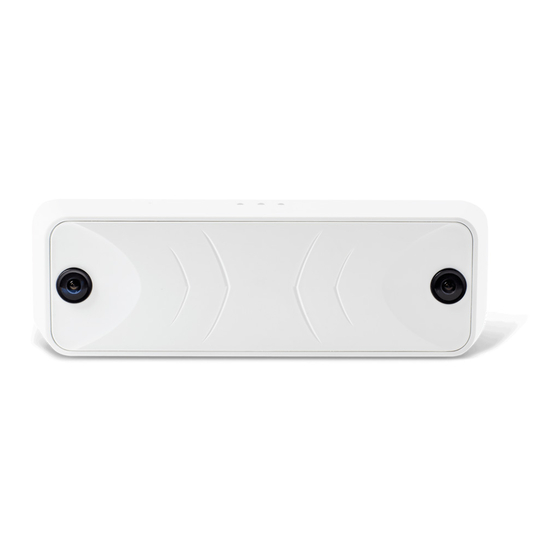
Technical Specifications 3D Alpha+: (Rectangular Cover): 225 x 70 x 40 mm Device Dimensions 3D Mini+: (Rectangular Cover): 127 x 127 x 38 mm 3D Alpha+: 257 x 224 x 91 mm Packing Dimensions (WxDxH) 3D Mini+: 250 x 167 x 82 mm 3D Alpha+: 382g Device Weight 3D Mini+: 236g... -
Page 6: General System Description
Local stored results can be queried by API calls to device. V-Count 3D Alpha+ can also act as a standard iBeacon. It can be used in various advertisement mobile projects. V-Count 3D Alpha+ device can also be used as Wi-Fi/Bluetooth Analysis projects component. - Page 7 Hilal projects are used for Staff Exclusion solutions. They detect and track the location of the V-Count BLE tags to count the entrances of staff to the store. Again, they are gathering the MAC Address of the V-Count BLE Tags.
-
Page 8: Installation
If the width/height ratio of the counting area is larger than a V-Count device; multiple devices will be used, as shown in Figure 3 FOV Multiple Devices. Sample installation can be seen in... - Page 9 Figure 4 Sample Installation of People Counter at the store entrance. For more specific orientations, please contact V-Count Technical Support. Figure 1 Head to Head Measurement Figure 2 FOV Violation 3D Alpha+ User’s Manual...
- Page 10 Figure 3 FOV Multiple Devices Figure 4 Sample Installation of People Counter at the store entrance 3D Alpha+ User’s Manual...
-
Page 11: Network And Electrical Architecture
POE connection (please see Appendix 4 for recommended POE models) Note: Electricity adapter and POE switch/injector is not supplied within the product package. User shall supply their own adapter or POE switch/injector according to V-Count’s qualified vendor list. In all these possible connection types, power backup with uninterruptable power supplies (UPS) is critical. - Page 12 Figure 6 Store diagram with adaptor and data cable connection Figure 7 Store diagram with POE connection 3D Alpha+ User’s Manual...
-
Page 13: Mounting
All V-Count devices use the same/similar mounting methods as described in this topic. 1. Select the suitable mounting bracket according to the site. If a catwalk floor is available to place the cables, use V-Count backside cover. If cable conduit will be used, apply V-Count bracket. -
Page 14: Field Installations Of Wi-Fi/Ble Projects
In staff exclusion projects there are 2 different methods. Standard installation where V-Count Alpha 3D+ devices are not used and Crescent method where V-Count Alpha 3D+ devices can be used as master or slave BLE devices. Standard and Crescent methods are selected according to store size and architecture to cover the whole store or only the entrance area. - Page 15 Standard Installation For small-sized and middle-sized stores (up to 1000 m ) standard installation shall be implemented. Trackers shall be placed inside store to cover the whole store with the signal ranges of the tracker devices. There are some triticale points to be considered while installing the devices: •...
- Page 16 Figure 12 Crescent installation with 1 master and 3 slaves Master and Slave devices shall be configured from the Setup Wizard pages. In stores having more than one entrance, one crescent model shall be installed to each entrance and only one master device shall be set.
-
Page 17: Calibration And Settings Of People Counter
Calibration and Settings of People Counter 5.1 Logging In System settings can be made by means of the server accommodated within V-Count. The system interface can be viewed from “https://V-Count_IP_Address:12102” using a web browser (Mozilla Firefox Google Chrome shall used) -
Page 18: Setup Wizard
Push Notification enables the device to transmit iBeacon signals for mobile apps for advertisements. This feature can be enabled only if the following steps are fulfilled: • Device must be connected to cloud.v-count.com over MQTT connection • Device must be defined as push notification enabled device on reporting tool. - Page 19 • Date: Power on date the V-Count device. Figure 15 Setup Wizard The system shall be calibrated through setup wizard for correct counting results. All the configuration pages are accessible from the menu connections on the upper bar of the page.
-
Page 20: Network Settings - Step 2
5.2.2 Network Settings – Step 2 In this page Network connection settings are set for device to connect to LAN. For “Wired” connection static IP or DHCP can be used. MAC Address of the device is listed below the corresponding menu. Figure 16 LAN Settings 3D Alpha+ User’s Manual... -
Page 21: Time Zone - Step 3
5.2.3 Time Zone – Step 3 In this page, installation location of the device is selected for the device to gather the correct date time settings from NTP server. Figure 17 Time Zone Settings 3D Alpha+ User’s Manual... -
Page 22: Mounting Height - Step 4
5.2.4 Mounting Height – Step 4 In this page, precise mounting height of the device shall be entered. This step is very important for auto calibration process of the device. The accurate measurement must be done between the device and the floor. Figure 18 Mounting Height Settings If the height is out of the range of the device a warning bar appears. -
Page 23: Floor Selection - Step 6
Another type of area is “Excluded” areas. These areas show where the counting shall not take place! They exclude the pixels from processing. They can be added and removed by using “Add New” and “Clear” buttons. Figure 20 Counting Region Settings 5.2.6 Floor Selection –... -
Page 24: Incoming - Outgoing Wires - Step 7
5.2.7 Incoming – Outgoing Wires – Step 7 In this page, incoming and outgoing wires are drawn. Each wire must have exactly 4 points. These lines indicate that the people counting direction of the visitor traffic. The arrow on the line shows which direction will be counted as incoming or outgoing. -
Page 25: Working Interval - Step 9
Min. Disparity: Enables to change distance value from cameras to objects in region of interest. This parameter effects the Depth image. Figure 23 Live Stream 5.2.9 Working Interval – Step 9 In this page, opening and closing hours of the store, shopping mall or the counting area shall be set. -
Page 26: System Settings
After setting Working interval; “Finish” button will finalize the Setup Wizard and require for a reboot. Rebooting the device make the new parameters online for the device. Figure 25 Finalizing Setup Wizard After rebooting checking the device connectivity to reporting tool and counting performance is highly recommended. -
Page 27: Remote Server
Figure 26 Web Server Settings After changing settings from this menu, a restart is required. 5.3.4 Remote Server In this page, connection methods to a reporting server is displayed. By default, all V-Count devices are set to connect to cloud.v-count.com address. - Page 28 The connection types are TCP and MQTT. cloud.v-count.com supports only TCP and MQTT connections. By default, MQTT is set at factory settings for connection to cloud.v-count.com. “Counting Period” is used to adjust the interval that device stores and sends the counting results to servers.
-
Page 29: Working Interval
“AWS” button writes a dummy file to V-Count’s s3-eu-west-1.amazonaws.com servers to test the connection to the V-Count buckets where video and log files are stored. This is enabled only with MQTT option. “AWS” button shall change to “Azure” when V-Count’s Azure server IP Address is set for MQTT connection. -
Page 30: System Commands
5.5 System Commands In this menu, system command button present. These are command buttons that does not link to any web interface page. They directly send commands to device. Figure 30 System Commands System commands are: • Reset Application: Only resets the application while the device still is powered on. •... -
Page 31: Advanced Settings
5.6 Advanced Settings 5.6.1 Logs In this page, system logs are reported. All the logs are written in spoken language to enable user to handle system errors or warnings easily. There are 6 levels of logging and off option in the system: •... -
Page 32: Video Record
• Maximum Record Time: Number of minutes to record video • Video Start Time: Start time of the video record • Send to counting team: Videos are directly sent to V-Count Video Counting team. If this is checked the counting shall be billed separately. Please contact to V-Count Technical Team before enabling this option. -
Page 33: Result Synchronization
If “Delete Former Records” is activated by selection “ON” then Maximum Record Validity Time is the maximum time duration results are kept internally in the device. If counting results are sent to cloud.v-count.com from the settings that are on Remote Server page; server continues to keep the results regardless of this parameter. -
Page 34: Calibration And Settings Of Wi-Fi/Ble Projects
Calibration and Settings of Wi-Fi/BLE Projects: 6.1 Wi-Fi/BLE Master Device: 6.1.1 Logging In System settings can be made by means of the server accommodated within V-Count. The system interface can be viewed from “https://V-Count_IP_Address:13102” using a web browser (Mozilla Firefox... -
Page 35: Setup Wizard
Push Notification enables the device to transmit iBeacon signals for mobile apps for advertisements. This feature can be enabled only if the following steps are fulfilled: • Device must be connected to cloud.v-count.com over MQTT connection • Device must be defined as push notification enabled device on reporting tool. - Page 36 Figure 36 Setup Wizard The system shall be calibrated through setup wizard for correct detection results. All the configuration pages are accessible from the menu connections on the upper bar of the page. By clicking “Start” button Setup Wizard shall continue with the next step. 3D Alpha+ User’s Manual...
- Page 37 6.1.2.2 Network Settings – Step 2 In this page Network connection settings are set for device to connect to LAN. For “Wired” connection static IP or DHCP can be used. MAC Address of the device is listed below the corresponding menu. Figure 37 LAN Settings 6.1.2.3 Time Zone –...
- Page 38 3D Alpha+ User’s Manual...
- Page 39 6.1.2.4 Working Interval – Step 4 In this page, opening and closing hours of the store, shopping mall or the counting area shall be set. Setting Monday will set all the week days. But also, other days can be set individually. For siesta or pray hours or for any other purposes, additional intervals in a day can be set from + signs.
- Page 40 Figure 40 Wi - Fi Processing Settings 6.1.2.6 BLE Devices – Step 6 In this page, slave devices that are at the center of crescent installation shall be set. If there is only 1 door and so there is only 1 crescent set installed this menu will be left empty. The serial IDs of slave devices that are at the center of other doors crescent model shall be set.
- Page 41 6.1.2.7 Remote Server – Step 7 In this page, connection methods to a reporting server is displayed. By default, all V-Count devices are set to connect to cloud.v-count.com address. Also, the Serial IDs of the devices are set at factory installation and not allowed to be changed afterwards.
- Page 42 Master and Slave devices can connect to 2 separate brokers that has different functionalities. One connection is to communicate with V-Count Reporting server and other one is used to communicate Master and Slave devices.
- Page 43 “AWS” button writes a dummy file to V-Count’s s3-eu-west-1.amazonaws.com servers to test the connection to the V-Count buckets where video and log files are stored. This is enabled only with MQTT option. “AWS” button shall change to “Azure” when V-Count’s Azure server IP Address is set for MQTT connection.
-
Page 44: 3System Settings
After rebooting checking the device connectivity to reporting tool and counting performance is highly recommended. 6.1.3 System Settings In this menu, there are quick access to setup wizard menu configuration pages and some extra configuration pages are present. 6.1.3.1 Network Settings This page is the same with the Setup Wizard 6.1.2.2. -
Page 45: 44 6.1.4 Counting Settings
6.1.4 Counting Settings In this menu, there are quick access to setup wizard menu configuration pages and some extra configuration pages are present. 6.1.4.1 Wi – Fi Settings This page is the same with the Setup Wizard Wi – Fi Processing – Step 5. Please refer the previous section. -
Page 46: Advanced Settings
6.1.6 Advanced Settings 6.1.6.1 Logs In this page, system logs are reported. All the logs are written in spoken language to enable user to handle system errors or warnings easily. There are 6 levels of logging and off option in the system: •... - Page 47 If “Delete Former Records” is activated by selection “ON” then Maximum Record Validity Time is the maximum time duration results are kept internally in the device. If counting results are sent to cloud.v-count.com from the settings that are on Remote Server page; server continues to keep the results regardless of this parameter.
-
Page 48: Wi-Fi/Ble Slave Device
6.2 Wi-Fi/BLE Slave Device: 6.2.1 Logging In System settings can be made by means of the server accommodated within V-Count. The system interface can be viewed from “https://V-Count_IP_Address:12108” using a web browser (Mozilla Firefox Google Chrome shall used) (For example https://192.168.1.31:12108). -
Page 49: Setup Wizard
Push Notification enables the device to transmit iBeacon signals for mobile apps for advertisements. This feature can be enabled only if the following steps are fulfilled: • Device must be connected to cloud.v-count.com over MQTT connection • Device must be defined as push notification enabled device on reporting tool. - Page 50 Figure 53 Setup Wizard The system shall be calibrated through setup wizard for correct detection results. All the configuration pages are accessible from the menu connections on the upper bar of the page. By clicking “Start” button Setup Wizard shall continue with the next step. 3D Alpha+ User’s Manual...
- Page 51 6.2.2.2 Time Zone – Step 2 In this page, installation location of the device is selected for the device to gather the correct date time settings from NTP server. Figure 54 Time Zone Settings 6.2.2.3 Working Interval – Step 3 In this page, opening and closing hours of the store, shopping mall or the counting area shall be set.
- Page 52 6.2.2.4 Remote Server– Step 4 In this page, connection methods to a reporting server is displayed. By default, all V-Count devices are set to connect to cloud.v-count.com address. Also, the Serial IDs of the devices are set at factory installation and not allowed to be changed afterwards.
- Page 53 “AWS” button writes a dummy file to V-Count’s s3-eu-west-1.amazonaws.com servers to test the connection to the V-Count buckets where video and log files are stored. This is enabled only with MQTT option. “AWS” button shall change to “Azure” when V-Count’s Azure server IP Address is set for MQTT connection.
- Page 54 6.2.2.5 Wi – Fi Processing – Step 5 In this page, parameters for Wi – Fi and BLE signal detection are set. These parameters are: Max Signal Value: Signals that are weaker than this signal value will be discarded. Be careful about the minus sign! For BLE projects Max Signal Value shall be set to -100.
-
Page 55: System Settings
After setting Wi-Fi Processing; “Finish” button will finalize the Setup Wizard and require for a reboot. Rebooting the device make the new parameters online for the device. Figure 61 Finalizing Setup Wizard After rebooting checking the device connectivity to reporting tool and counting performance is highly recommended. -
Page 56: Counting Settings
6.2.3.2 Web Server In this page, web interface port and usernames and passwords can be changed. The username and password changes are only accessible by Super Admin user only. Figure 62 Web Server Settings After changing settings from this menu, a restart is required. 6.2.3.3 Remote Server This page is the same with the Setup Wizard 6.2.2.4. -
Page 57: Advanced Settings
Figure 63 System Commands System commands are: • Reset Application: Only resets the application while the device still is powered on. • Reboot: Soft power cycle the device • Logout: Logouts the current web interface session “Reset Application” and “Reboot” are required after some system settings. 6.2.6 Advanced Settings 6.2.6.1 Logs In this page, system logs are reported. - Page 58 • Engine_DateTime.log: These logs are named with the creation date of the file. One file size is limited to 5MB. Also at every midnight file is ended regardless of the size. And a new file is started for the new day. Figure 64 Logs By default, Logs level is set to “Notice”.
- Page 59 If “Delete Former Records” is activated by selection “ON” then Maximum Record Validity Time is the maximum time duration results are kept internally in the device. If counting results are sent to cloud.v-count.com from the settings that are on Remote Server page; server continues to keep the results regardless of this parameter.
-
Page 60: Leds And Reset Button
LEDs and Reset Button: 7.1 LED Status As seen below, V-Count Alpha has 3 LEDs and a reset button on it: • LED1: Power led • LED2: Camera led • LED3: Network led • Reset Button Figure 66 Indicator LEDs When the device is powered on over adaptor or POE, LED1 is turn on as Green. - Page 61 • SSH Port: 12104 • Admin Username: admin • Admin Password: qw34qw34 Reset procedure is as follows: • Hold down the Reset button for at least 10 seconds until observing the following LED status: o LED1 continues to be Green at whole process o LED2 is Red for 1 second, LED3 is off o LED2 is off, LED3 is Red for 1 second o This loop continues for 5 times.
-
Page 62: Faq
In this topic please follow any point step by step. Try the first recommended solution, examine the result then continue with the next step. 1. I cannot reach V-Count device through “ping”. • Check the network settings of the device. It can have been changed by the system integrator. - Page 63 • Check the counting environment. Customer traffic way can be changed. Recheck counting wires and mask. 5. After a while connection to the device is lost and the device does not send any data to the server. • Control web interface connection and system logs. If the device cannot be pinged continue with the corresponding FAQ step.
-
Page 64: Appendix 1 - Accuracy Verification
PM=Sum people entering detected by the Manual Counting from videos (All entries) For example, if V-Count reporting page shows 356 for a defined time interval and the manual counting from the raw video is 349 the error rate would be 2% where the accuracy of the system will be 98%. -
Page 65: Appendix 2 - Changing Pc Ip Address And Accessing Device
Appendix 2 – Changing PC IP address and accessing device To access to the device, a static IP number must be set to user’s computer and that IP number must be on the same IP block with the device’s IP number. Factory default IP address can be found at the label on the back of the device. -
Page 66: Setting Ip Address Of Macos
Setting IP Address of MacOS Open “System Preferences” from LaunchPad Figure 68 LaunchPad - System Preferences Open “Network” in System Preferences Figure 69 System Preferences In network select Local Lan Connection and on the right menu select “Manually” for “Configure IPv4” and enter IP address for the MacOS. 3D Alpha+ User’s Manual... - Page 67 Figure 70 Setting IP Address Apply the settings and now you can ping and connect to device. 3D Alpha+ User’s Manual...
-
Page 68: Setting Ip Address Of Windows 10
Setting IP Address of Windows 10 Open “Network and Sharing Center” by right clicking on the network icon on the bottom left side of the screen. Figure 71 Network and Sharing Center On the new window click the “Ethernet” Figure 72 Active Networks Select Properties ➔... - Page 69 Google Chrome or Mozilla Firefox must be used to access this web interface. Any other web browsers are not supported. (i.e. Internet Explorer, Safari, etc. are not supported) While accessing the device, browsers may ask for adding an exception for the V-Count devices. Click Advanced ➔ Confirm Security Exception.
-
Page 70: Appendix 3 - Network Communication Ports
Appendix 3 – Network Communication Ports Figure 75 Network Architecture 3D Alpha+ User’s Manual... -
Page 71: Appendix 4 - Recommended Poe Injector And Switch Models
Appendix 4 – Recommended POE Injector and Switch Models Please refer to V-Count Hardware Specifications Sheet document. 3D Alpha+ User’s Manual...
Need help?
Do you have a question about the 3D Alpha+ and is the answer not in the manual?
Questions and answers