
Related Manuals for STIHLER ELECTRONIC ASTOPAD


Summary of Contents for STIHLER ELECTRONIC ASTOPAD
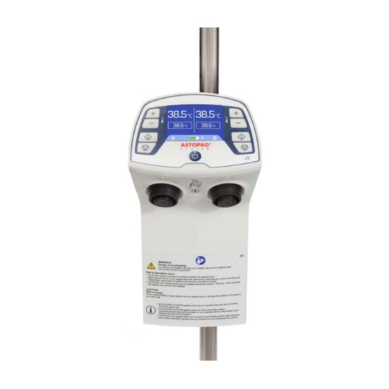
- Page 1 Instructions for use ® ASTOPAD Patient Warming System STIHLER ELECTRONIC GmbH • 70597 Stuttgart • Germany...
- Page 2 To be completed by the user: Serial number Registration number Device location Start-up date Manufacturer: STIHLER ELECTRONIC GmbH Julius-Hoelder-Strasse 36 70597 Stuttgart GERMANY Tel. +49 (0) 711-720670 Fax +49 (0) 711-7206757 www.stihlerelectronic.de E-Mail: info@stihlerelectronic.de © 2020 STIHLER ELECTRONIC GmbH...
-
Page 3: Table Of Contents
5 Symbols ......................15 6 Product description ..................19 6.1 Introduction ..........................19 6.2 Technical description ........................ 19 6.3 Components of the ASTOPAD ....................21 6.4 Control panel ..........................23 7 Operating states ....................24 7.1 Standby mode........................... 24 7.2 On mode ........................... 25 7.3 Heating mode output A and/or B .................... - Page 4 ® ASTOPAD Instructions for Use 11 Information messages and troubleshooting ..........44 11.1 No applied part connected ...................... 44 11.2 Battery state ........................... 44 11.2 Battery defective ........................45 11.3 Applied part temperature too low .................... 45 11.4 Applied part temperature too high ................... 46 12 Brief overview of operating states and alarms ...........
-
Page 5: Information About These Instructions
If the equipment is damaged during the guarantee period, send the cleaned equipment to the nearest sales point or directly to STIHLER ELECTRONIC GmbH. The sender is responsible for any transport and packaging costs. -
Page 6: Disposal Of The Equipment
Transport rule for the return of device with built-in battery: When returning ASTOPAD DUO310 control units, it is essential to ensure that the control unit is in storage / transport condition (see chapter 7.6 "Storage / transpor- tation"). -
Page 7: Service Information
Before you call a service … To help us better serve you, please have the serial numbers of your ASTOPAD system (control unit & applied part) ready when you call for parts or service. The serial number is located on the type label attached the control unit’s rear and on the backside of the junction block of the applied parts. -
Page 8: Warnings
• With transdermal drug applications (patches), the additional heat can in- crease the uptake of the drugs and result in injury to the patient. • In the case of arterial occlusion, the applied parts of the ASTOPAD may not be used distal to this area. - Page 9 WARNING Risk of injury! • When applied parts ASTOPAD COV are used as a top blanket, ensure that they do not obstruct the patient’s field of vision. • Do not use the ASTOPAD until the following error conditions have been rem- edied through appropriate corrective action: - Damaged or worn cables, plugs, or connecting socket.
- Page 10 • Do not place the patient on the connection block of the applied part. • When the ASTOPAD COV applied parts are used as an under-blanket, en- sure that they are placed flatly underneath the patient, are secured, and will not crease.
-
Page 11: Cautions
• Do not continue to use ASTOPAD applied parts beyond the labeled Use by Date. CAUTION Risk of hypothermia! • If the alarm shut-off of the ASTOPAD is triggered at an output, the entire system will switch off. • If thermally conductive materials, such as water, gel, and similar substances, are used and were not pre-heated, the patient’s body temperature may reduce as a... -
Page 12: Notices
• The temperature control of the ASTOPAD controls and monitors the temperature of the applied parts, but not the patient’s body temperature. • If the ASTOPAD cannot be started or if the patient's temperature balance is insuf- ficient, consider the use of alternative warming methods in order to avoid or re- duce hypothermia or to improve the patient's well-being. -
Page 13: Intended Use
No contraindications are known for patient warming. 4.3 Possible adverse effects In normal use, no side effects arising from ASTOPAD are to be expected. For longer surgical procedures there is an increased pressure ulcer risk for the pa- tient. To reduce the pressure ulcer risk, therefore, the additional use of a pres- sure-relieving support is recommended after an operating time of two hours. -
Page 14: Intended Environment Of Use / Operation
• Appropriate medical hygienic factors must be applied for the use of ASTOPAD. • ASTOPAD must not be used in an environment at risk of explosion or in the present of flammable anesthetics. • The ASTOPAD can be used in surgical, intensive care or inpatient areas in which there is a risk of cooling for the patient, or where the patient requires external warming. -
Page 15: Symbols
® ASTOPAD Instructions for Use 5 Symbols Symbols and indications on the control panel The Standby button switches between the Standby mode and the On mode. The device is in Standby mode if the blue LED illuminates. “Start” button: Starts the heating process. - Page 16 ® ASTOPAD Instructions for Use Where applicable, these symbols appear at the appropriate location on the patient warming system, on the packaging, on the identification plate, or in the accompany- ing documentation. Defibrillation-proof type BF applied part in accordance with IEC/EN 60601-1.
- Page 17 ® ASTOPAD Instructions for Use Additional information Electrical devices are recoverable waste and should not be dis- posed of in domestic waste at the end of their service life. Batteries and rechargeable batteries are recoverable waste and should not be disposed of in domestic waste at the end of their service life.
- Page 18 ® ASTOPAD Instructions for Use Prohibition: Do not clamp – risk of damage and possible overheating! Prohibition: Never insert pointed or sharp objects into the applied parts – risk of damage and possible overheating! Prohibition: Do not disinfect with hypochlorite solution...
-
Page 19: Product Description
Risk of overheating! • For pediatrics under 90 cm in length/height, use only the applied part ASTO- PAD COV070. • Do not use ASTOPAD COV105 or COV155 or COV180 for pediatrics under 90 cm in length/height. 6.2 Technical description The ASTOPAD control unit (DUO310) is equipped with a universal mounting... - Page 20 ® ASTOPAD Instructions for Use The ASTOPAD DUO310 control unit does not control and indicate the actual temperature of the patient, but rather only the actual temperature of the applied part. Temperature regulation of the individual applied parts is performed with several integrated sensors.
-
Page 21: Components Of The Astopad
® ASTOPAD Instructions for Use 6.3 Components of the ASTOPAD Control unit Designation Description Operating buttons and Control panel temperature displays. For secure attachment of Attachment device the ASTOPAD DUO310 control unit. Output A Plug connection between (connecting socket) control unit and applied Output B part. - Page 22 It pro- tects the contacts and guarantees the IPX2 liq- uid ingress protection. The extension connection cable is used to connect Extension connection the ASTOPAD COV ap- cable plied parts to the control unit. Fig. 2 ASTOPAD COV applied parts...
-
Page 23: Control Panel
® ASTOPAD Instructions for Use 6.4 Control panel Fig. 3 Control panel No. Designation Description Actual temperature Displays the actual temperature of the applied part A or B Set temperature Displays the selected set temperature of the applied A or B part. -
Page 24: Operating States
® ASTOPAD Instructions for Use 7 Operating states 7.1 Standby mode Control panel After connecting the mains plug to the mains socket, the con- trol unit is in Standby mode Action Press the “Standby” button to switch the device from any mode to Standby mode. -
Page 25: On Mode
® ASTOPAD Instructions for Use 7.2 On mode Control panel Press the “Standby” button to switch the device from Action Standby mode to On mode. • The Standby LED turns off. • The Start screen is displayed for 1 sec. -
Page 26: Heating Mode Output A And/Or B
® ASTOPAD Instructions for Use 7.3 Heating mode output A and/or B Control panel Action Press the “Start” button to start the heating process. • The acoustic alarm switches off, and the “Alarm” turns off. • When the applied part is started, the display shows the symbol “Applied part heating”... -
Page 27: Increasing/Decreasing The Set Temperature
® ASTOPAD Instructions for Use 7.4 Increasing/decreasing the set temperature Control panel Press the “Temperature increase” /“temperature de- crease” button to raise or lower the selected set temper- Action ature in 0.5 °C increments. Confirm the new set temperature by pressing the “Start”... -
Page 28: Switching Off An Output (A Or B)
® ASTOPAD Instructions for Use 7.5 Switching off an output (A or B) Control panel Action Press the “Stop” button to switch off an output. • The “Start” LED turns off. Device • Displays turn off for the output that was switched response off. -
Page 29: Installation
With this, the device can be securely attached to infusion stands as well as to medical standard rails. CAUTION Risk of injury! When installing the ASTOPAD DUO310 control unit on an infusion stand, ob- serve the instructions from the infusion stand manufacturer regarding maximum load and tilting stability. 8.2.1 Attachment to infusion stands 1. -
Page 30: Getting Started
• With transdermal drug applications (patches), the additional heat can increase the uptake of the drugs and result in injury to the patient. • In the case of arterial occlusion, the applied parts of the ASTOPAD may not be used distal to this area. - Page 31 Instructions for Use WARNING Risk of injury! • Do not use the ASTOPAD until the following error conditions have been rem- edied through appropriate corrective action: - Damaged or worn cables, plugs, or connecting socket. - Damaged housing, damaged or loose control panel - Damaged or missing markings/safety signs/warnings.
-
Page 32: Preparation For Use
If a pressure-relieving gel pad is used in combination with the applied parts ASTOPAD COV070/COV105/COV150/COV180 on the OR table, the gel pad must be placed under the ASTOPAD COV. Observe the arrangement of the ASTOPAD COV and the gel pad. The gel pad and COVXXX must be positioned flush with the head or foot end of the OR table. -
Page 33: Starting The Heating Process
9.1.2 Using ASTOPAD COV as a top blanket WARNING Risk of injury! When applied parts of the ASTOPAD COV are used as a top blanket, ensure that they do not obstruct the patient’s field of vision. Always place a thin waterproof and absorbent barrier between the ASTOPAD applied part and the patient. -
Page 34: Selecting A New Set Temperature
9.5 Switching off the ASTOPAD 1. Press the “Standby” button of the ASTOPAD DUO310 control unit to switch off (all displays are turned off, the “Standby” LED illuminates). 2. Disconnect the ASTOPAD DUO310 control unit from the applied part(s). 3. Clean and disinfect ASTOPAD. -
Page 35: Cleaning And Disinfection
9.6.2 Applied parts 1. Disconnect applied part from the control unit. 2. Close the connector using the end cap (refer to Fig. 2 ASTOPAD COV ap- plied parts) to protect electrical contacts from entering liquids. 3. Visually inspect all surfaces (all sides) including the junction block and the connecting cable for wear and tear, cuts, holes and cracks and other unac- ceptable deteriorations. - Page 36 ® ASTOPAD Instructions for Use When soil or residues of body fluids are visible 5. Clean first according to the instructions of the disinfectant manufacturer and then disinfect in a second step. If the surface is not visually clean at the end of the cleaning step, the cleaning process should be either repeated or the device should be safely disposed.
-
Page 37: Alarms And Troubleshooting
In case of failure of the equipment, possible injury to the patient is delayed and the operator has sufficient time to provide alternative warming methods. To ensure the safe operation of the ASTOPAD for patients and users, the ASTOPAD is equipped with a series of independent alarm systems. The alarms are the result of consistent implementation of the standards listed in Section 15 Conformity with international standards. -
Page 38: Low Temperature Alarm "A1
►Send the applied part to the local sales point. Required action(s) Press the “Start” button to return the ASTOPAD to the for resetting control mode. The acoustic alarm signal is then sup- pressed for a further 10 minutes and the display shows the symbol “Applied part heating”... -
Page 39: Overheating Alarm "A2
Applied part defective. ►Send the applied part to the local sales point. Required action(s) Press the “Start” button to return the ASTOPAD to the for resetting control mode. As soon as the set temperature is reached or the alarm is reset, the acoustic overheating alarm “A2”... -
Page 40: Time Alarm "A3
® ASTOPAD Instructions for Use 10.3 Time alarm “A3” (low priority alarm condition) Control panel • When the applied part is started, the display shows “A3”. • Device response The Start LED flashes and the Alarm LED turns • An acoustic alarm signal is triggered. -
Page 41: Overheating Alarm Shut-Off "A4
® ASTOPAD Instructions for Use 10.4 Overheating alarm shut-off “A4” (medium priority alarm condition) Control panel • When the applied part is started, the display shows “A4”. • Device response The Start LED and the Alarm LED flash. • An acoustic alarm signal is triggered. -
Page 42: Sensor Defect Alarm "A5
® ASTOPAD Instructions for Use 10.5 Sensor defect alarm “A5” (medium priority alarm condition) Control panel • The display for the affected output shows “A5”. • The Start LED and the Alarm LED flash. Device response • An acoustic alarm signal is triggered. -
Page 43: Heater Defect Alarm "A6
® ASTOPAD Instructions for Use 10.6 Heater defect alarm “A6” (medium priority alarm condition) Control panel • The display for the affected output shows “A6”. • The Start LED and the Alarm LED flash. Device response • An acoustic alarm signal is triggered. -
Page 44: Information Messages And Troubleshooting
►Connect at least one applied part to one of the ►Required outputs A/B. action(s) The display is shown until at least one applied part is connected to the ASTOPAD DUO310 control unit. 11.2 Battery state (only for battery-operated equipment) Control panel Display battery state:... -
Page 45: Battery Defective
® ASTOPAD Instructions for Use 11.2 Battery defective (only for battery-operated equipment) Control panel After the Start screen, in mains operation mode and in Device response Standby mode the display shows the crossed-out battery symbol. This display appears if the battery is defective or an Information original battery has not been inserted. -
Page 46: Applied Part Temperature Too High
® ASTOPAD Instructions for Use 11.4 Applied part temperature too high Control panel The display shows an “H”. Device response This display appears if the temperature of the applied part Information condi- is outside of the display range. tion Possible reasons Temperature of the applied part >... -
Page 47: Brief Overview Of Operating States And Alarms
® ASTOPAD Instructions for Use 12 Brief overview of operating states and alarms 12.1 Overview of operating states Operating Display “Start” “Alarm” “Standby” Acous- Possible state reasons Output alarm A or B signal Green Yellow Blue Standby mode Battery is being... - Page 48 ® ASTOPAD Instructions for Use Operating Display “Start” “Alarm” “Standby” Acous- Possible state reasons Output alarm A or B signal Green Yellow Blue Actual temperature Set temperature Warm-up phase No applied part Actual temperature connected, or Set temperature defective sensor in...
-
Page 49: Overview Of Alarms
® ASTOPAD Instructions for Use 12.2 Overview of alarms “Start” “Alarm” “Standby” Acous- Alarm Display Possible reasons Output alarm A or B signal Green Yellow Blue Actual temperature Low tempera- Actual temperature Set temperature ≤1.0 °C set ture alarm temperature “A1”... -
Page 50: Maintenance
Risk of injury! • The service personnel must be appropriately trained and qualified. • The ASTOPAD does not contain any parts the user can repair. Therefore, do not attempt to repair the ASTOPAD yourself. Contact your local sales point. • Any repairs to the device may only be carried out by persons authorized and qualified by the manufacturer. -
Page 51: Replacing The Battery
- Alternative patient leakage current The tests must be performed according to the specifications in the test instructions (Scope of delivery of the ASTOPAD test box) 13.2 Replacing the battery 1. Disconnect the device completely from the mains power supply (by discon- necting the mains plug) 2. -
Page 52: Technical Data
® ASTOPAD Instructions for Use 14 Technical data ASTOPAD DUO310 Control unit compatible with ASTOPAD applied parts COV 100 – 240 VAC Electrical connection 50 – 60 Hz Rated current 110 V = 1,6 A, 240V = 0,8 A Primary fuses 2 x 3.15 A... - Page 53 ® ASTOPAD Instructions for Use ASTOPAD DUO310 Control unit compatible with ASTOPAD applied parts COV Control of contact surface temperature 32.0 °C to 39.0 °C in 0.5 °C increments (Essential Performance ac- Tolerance ± 1.0 °C cording to IEC/EN 80601-2-35) Contact surface temperature ±...
- Page 54 The specified defibrillation protection is ensured only when the applied part is con- nected to the control unit. DANGER Explosion hazard! Do not use the ASTOPAD patient warming system in an explosion-hazard envi- ronment or in the presence of flammable anesthetics.
-
Page 55: Conformity With International Standards
® ASTOPAD Instructions for Use 15 Conformity with international standards Standard Title IEC/EN 60601-1 ANSI/AAMI ES Medical electrical equipment – Part 1: General 60601-1 requirements for basic safety, including essential performance CAN/CSA C22.2 No. 60601-1 Medical electrical equipment – Part 1-2: General... -
Page 56: Ordering Information And Accessories
Instructions for Use 16 Ordering information and Accessories Ref. -Variant Description Control unit compatible with ASTOPAD applied parts COV/SOF/ROE ASTOPAD DUO310 control unit, 100-240 VAC, 50-60 Hz, DUO310 -NA Hospital Grade plug Built-in, rechargeable battery for ASTOPAD DUO310 control unit 1831.0001... -
Page 57: Guidelines And Manufacturer's Declaration
17 Guidelines and manufacturer’s declaration Guidance and manufacturer's declaration - electromagnetic emissions ASTOPAD is intended for use in the electromagnetic environment specified below. The customer or user of the ASTO- PAD should assure that it is used in such an environment. - Page 58 RF transmitters, an electromagnetic site survey should be considered. If the measured field strength in the location in which the ASTOPAD is used exceeds the applicable RF compliance level above, the ASTOPAD should be observed to verify normal operation. If abnormal performance is observed, additional measures may be necessary, such as reorienting or relocating the ASTOPAD.
- Page 59 ® ASTOPAD Instructions for Use...
Need help?
Do you have a question about the ASTOPAD and is the answer not in the manual?
Questions and answers