STIHLER ELECTRONIC ASTOTHERM plus Repair Instructions
Blood and infusion warmer
Hide thumbs
Also See for ASTOTHERM plus:
- Instructions for use manual (51 pages) ,
- Instructions for use manual (65 pages)
Table of Contents
Advertisement
Advertisement
Table of Contents
Troubleshooting

Related Manuals for STIHLER ELECTRONIC ASTOTHERM plus


Summary of Contents for STIHLER ELECTRONIC ASTOTHERM plus
- Page 1 ® ASTOTHERM plus Blood and Infusion Warmer Models AP200, AP220 and AP260 Models AP200S, AP220S and AP260S with ASTOLINE Repair Instructions REVISION 6, 03/2010 STIHLER ELECTRONIC GmbH Julius-Hoelder-Strasse 36 D-70597 Stuttgart Phone: +49 (0)711-720670 Fax: +49 (0)711- 7206757 Part-No. 9950.9000.12...
- Page 2 ASTOTHERM PLUS Repair Instructions Page 2 Revision: 6 – 03/2010...
-
Page 3: Table Of Contents
Description of the electronics...........................7 Technical Data ..............................9 Terminal connecting plan..........................11 ASTOTHERM PLUS spare parts........................12 GENERAL GUIDELINES AND PRINCIPLES FOR THE REPAIR OF ASTOTHERM PLUS BLOOD AND INFUSION WARMERS ............................19 Technical Service and Ordering Spare Parts ....................19 Guarantee repairs ............................19 Liability ................................19 Important instructions.............................20... - Page 4 ASTOTHERM PLUS Repair Instructions User information: Test results which must be achieved to ensure safe operation are outlined by a frame. The description for dismantling covers every possible assembly group and step. If a defective component or an assembly group are to be replaced, only the steps necessary for this should be performed.
-
Page 5: Technical Description
Technical description General Applications The ASTOTHERM PLUS allows fluids supplied to patients to be heated, either to avoid or reduce hypothermia or to increase well-being. Applications include transfusions, infusions, dialysis, haemofiltration and apheresis. The warmer works in accordance with the principle of flow heating, i.e. the heat is transmitted by the heat exchanger via the sterile infusion extension to the fluid flowing within it. -
Page 6: Structure
ASTOTHERM PLUS Repair Instructions There are ASTOTHERM PLUS in the following variations Order no Heat exchanger Temperature Power ASTOLINE groove consumption actively-heated insulation up to the patient AP 200* 4 mm 40°C (fixed) 250 W AP 200 S* 4 mm 40°C (fixed) -
Page 7: Description Of The Electronics
ASTOTHERM PLUS Repair Instructions Description of the electronics C Temperature control: The temperature at the heat exchanger cylinder is controlled by a control unit consisting of a microprocessor, an A/D converter and a triac unit. The actual temperature is determined by two NTC sensors at the inlet (NTC1) and outlet (NTC2) (cf. - Page 8 ASTOTHERM PLUS Repair Instructions C Watchdog device: The microprocessor is continuously monitored by a so-called watchdog circuit. If the microprocessor becomes defective due to a malfunction, the watchdog circuit emits a signal and the device goes to stand-by mode. C Mains power failure bridging: This is used to restart the device automatically in the previously selected state in the event of a brief power failure.
-
Page 9: Technical Data
ASTOTHERM PLUS Repair Instructions Technical Data 1.4.1 ASTOTHERM PLUS 200 and 200S AP200(S) EU AP200(S) UK AP200(S) CH AP200(S) DK AP200(S) NA ASTOTHERM PLUS 200(S) Line voltage 230-240 VAC "10% 100-115 VAC "10% 47-63 Hz 47-63 Hz DK - plug... - Page 10 ASTOTHERM PLUS Repair Instructions 1.4.2 ASTOTHERM PLUS 220, 220S and 260, 260S ASTOTHERM PLUS 220(S) AP220(S) EU AP220(S) UK AP220(S) CH AP220(S) DK AP220(S) NA AP260(S) EU AP260(S) UK AP260(S) CH ASTOTHERM PLUS 260(S) AP260(S) DK AP260(S) NA 230-240 VAC "10% 100-115 VAC "10%...
-
Page 11: Terminal Connecting Plan
ASTOTHERM PLUS Repair Instructions Terminal connecting plan Fig. 2 Connections between electronic components Revision: 6 – 03/2010 Page 11... -
Page 12: Astotherm Plus Spare Parts
ASTOTHERM PLUS Repair Instructions ASTOTHERM PLUS spare parts Fig. 3 Cross section of the ASTOTHERM PLUS Page 12 Revision: 6 – 03/2010... - Page 13 ASTOTHERM PLUS Repair Instructions Fig. 4 Cross-section of bottom part assembly with optional components Revision: 6 – 03/2010 Page 13...
- Page 14 ASTOTHERM PLUS Repair Instructions Fig. 5 Cross-section of top part assembly with optional components Page 14 Revision: 6 – 03/2010...
- Page 15 ASTOTHERM PLUS Repair Instructions ASTOTHERM PLUS spare parts When ordering please indicate always model number and serial number! Order number Name consist of TOP PART OF HOUSING AP 200 9751.4205.00 complete with handle, bolts and front panel 9750.4205.00 TOP PART OF HOUSING AP 220/260 complete with handle, bolts and front panel 9751.4202.00...
- Page 16 ASTOTHERM PLUS Repair Instructions When ordering please indicate always model number and serial number! 9750.4100.10 POWER SUPPLY CORD SCHUKO 1Power supply cord SCHUKO 1Cable tie 90mm 9750.4100.12 POWER SUPPLY CORD GREAT BRITAIN 1Power supply cord GREAT BRITAIN 1Cable tie 90mm 9750.4100.16...
- Page 17 ASTOTHERM PLUS Repair Instructions When ordering please indicate always model number and serial number! 9750.3132.00-41 HEAT EXCHANGER COMPLETE 1) 6) 7) GROOVE 4 MM (AP200, 220) 40/41°C 1Earth conductor 200mm mounted 4Insulating cover 1Ferrit-Ring 2Cable tie 90mm 9750.3132.00-43 HEAT EXCHANGER COMPLETE 1) 6) 7) GROOVE 4 MM (AP220) 43°C...
- Page 18 ASTOTHERM PLUS Repair Instructions When ordering please indicate always model number and serial number! 9750.8230.20 AL-PLUG (for soldering) 1 AL arrow sticker 9750.4201.14 SET O-RINGS 4x1 MM 4 for housing screws 2 for handle 2Cable tie 90mm 9750.5101.11 SET O-RINGS 5x1 MM...
-
Page 19: General Guidelines And Principles For The Repair Of Astotherm Plus Blood And Infusion Warmers
If damage occurs during the guarantee period, please clean the device and send it to a sales location near you or directly to STIHLER ELECTRONIC. The costs of transport and packaging are for the sender's account. Liability... -
Page 20: Important Instructions
ASTOTHERM PLUS Repair Instructions Important instructions All tests must be carried out by properly qualified staff, i.e. staff who have the relevant expert professional training, knowledge and experience and are familiar with the relevant technologies, standards and local rules and regulations. Personnel who have to assess safety must be able to recognise any consequences and dangers caused by devices which do not comply with the requirements. -
Page 21: Procedure For Astotherm Plus Repairs
ASTOTHERM PLUS Repair Instructions Procedure for ASTOTHERM PLUS repairs Fig. 7 Flow chart for repairs Revision: 6 – 03/2010 Page 21... -
Page 22: Cleaning And Disinfecting
(< 0,2 %) of aldehydes. For disinfecting the ASTOTHERM PLUS and the ASTOLINE, we recommend Bacillol plus from Bode Chemie in Hamburg, Meliseptol from B. Braun in Melsungen and Mikrozid Liquid or Mikrozid Pumpspray from Schülke &... -
Page 23: Check Display Devices (Lcd And Led)
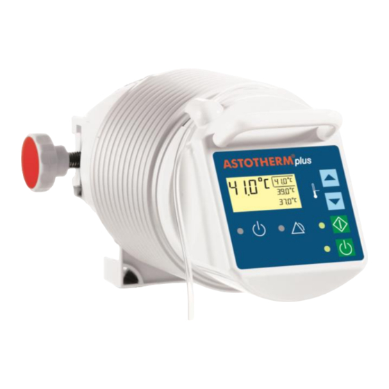
ASTOTHERM PLUS Repair Instructions Check display devices (LCD and LED): Connect the device to the mains at room temperature. All the display devices should come on for a brief period (cf. Figs 8 and 9). Fig. 8 Display elements of model 200(S) Fig. -
Page 24: Check Temperature In Control State
ASTOTHERM PLUS Repair Instructions Check temperature in control state (better with heat protection sleeve) The test thermistor (order-No. 9950.9000.35), a calibrated ohmmeter and the table of resistance/temperature in the appendix of these repair instructions are required for this purpose. Insert the test thermistor into the rear measuring bore on the side of the heat exchanger (see Fig. 10) and connect it with the ohmmeter. -
Page 25: Alarm Test Functions
ASTOTHERM PLUS 220(S) and 260(S) models with adjustable selected temperature. For the ASTOTHERM PLUS 200(S) models, there are no keys for changing temperature. In this case, the key names in brackets apply (cf. Figs 8 and 9 and operating instructions, Section “CONTROL PANEL”). - Page 26 ASTOTHERM PLUS Repair Instructions CAUTION Please observe the following instructions: 1. Warmer has to be calibrated and if necessary to be adjusted 2. Warmer needs to work in the control state for a few minutes to ensure that the heat exchanger is heated through evenly.
-
Page 27: Measuring Resistance Of Astoline Active Insulation
ASTOTHERM PLUS Repair Instructions Functional check of devices with ASTOLINE active insulation (Models 200S, 220S, 260S only) Measuring resistance of ASTOLINE active insulation Using a resistance measuring device, measure the electrical resistance between Pin 1 and Pin 3 on the plug of the flexible silicone groove (see Fig. -
Page 28: Troubleshooting
ASTOTHERM PLUS Repair Instructions Troubleshooting If one or more items of the functional check are failed, then troubleshooting will be required. Compare the activities of the display devices with the operating and alarm states also described in the operating instructions (Section “CONTROL PANEL”). - Page 29 ASTOTHERM PLUS Repair Instructions Fault Possible causes Remedy Heating system defective Measure resistance of heating system. Device can be started, but heat In event of deviation from specified value (see exchanger cylinder does not get Section 6.4): Y Change heat exchanger and calibrate the unit.
-
Page 30: Dismantling
ASTOTHERM PLUS Repair Instructions Dismantling Generally-applicable safety conditions and precautions apply to dismantling the ASTOTHERM PLUS. All electrical installations must comply with the applicable national standards and regulations in each case. During dismantling, ensure that the device is reliably disconnected from the mains. Electronic components can contain a residual current even after the device is switched off. -
Page 31: Dismantling Bottom Part Assembly
Prevent the heat exchanger/transformer board assembly from rolling away. The device is now dismantled into individual groups. Fig. 15 ASTOTHERM PLUS and ASTOLINE dismantled into assemblies Revision: 6 – 03/2010 Page 31... -
Page 32: Dismantling Bottom Part Assembly
ASTOTHERM PLUS Repair Instructions Dismantling bottom part assembly Mains cable and screw connection: a) Undo the union nut of the cable gland until the mains cable can be pulled out. Place the bottom part on the fixing unit. b) Should the cable gland have to be completely dismantled, the nut on the inside needs to be undone using a double cranked hex ring spanner (WAF 22). -
Page 33: Dismantling The Top Part Assembly
ASTOTHERM PLUS Repair Instructions Dismantling the top part assembly CAUTION When handling the top part, ensure that the bolts are not put under lateral strain - this can lead to fracture of the bolts or of the housing domes. Operating board: a) Place the top part on its front. -
Page 34: Dismantling The Device Fixing Assembly
ASTOTHERM PLUS Repair Instructions Dismantling the device fixing assembly Dismantling for cleaning purposes: a) Push the bolts out of the base plate using a drift. b) Push the base plate off the clamps. c) Unscrew the clamp on the right of the threaded shaft. Remove the rectangular nut on the right and unscrew the knurled screw. -
Page 35: Assembling The Device
ASTOTHERM PLUS Repair Instructions Assembling the device The safety information in Section 6 applies to assembly of the ASTOTHERM PLUS device! Procedure for assembly: assembly steps are described in individual sections by assembly group. Assembling the device fixing assembly a) Prepare all the parts as shown in Fig. 16. Ensure that the base plate with the depression for the rating plate is facing upwards. - Page 36 ASTOTHERM PLUS Repair Instructions d) Clamp the fixing strip on the correct side on the front between the edge of the heat exchanger and the transformer board. The fixing strip has an opening for the bimetallic switch of the heating system.
-
Page 37: Assembly Of The Top Part Assembly
ASTOTHERM PLUS Repair Instructions h) Turn the unit round. Connect the earth wire and the heating cable to the transformer board in accordance with mains voltage (see printed information on the transformer board). Assembly of the top part assembly CAUTION When handling the top part, ensure that the bolts are not put under lateral strain. - Page 38 ASTOTHERM PLUS Repair Instructions Operating board: Fit the key extensions to the keys of the operating board. The key extensions must lie level on the keys. g) Push operating board into the lateral guide rails of the housing at an angle and suspend behind the bottom mounting screws.
-
Page 39: Assembling The Bottom Part Assembly
ASTOTHERM PLUS Repair Instructions Assembling the bottom part assembly Device fixing: a) Place the preassembled device fixing (as per Section 7.1) on the clamps so that the handwheel points to the left. b) Insert o-ring seals in the depressions of the base plate at the screw bores. - Page 40 ASTOTHERM PLUS Repair Instructions Devices with equipotential bonding plug: Push the O-ring seal over the thread of the equi- potential bonding plug and insert this in the housing bore from the outside. k) Put on the washer and tighten the nut with an open- ended spanner (WAF 10).
-
Page 41: Final Assembly Of Assemblies
ASTOTHERM PLUS Repair Instructions Final assembly of assemblies Once the individual assemblies are prepared, they can be joined to form a complete ASTOTHERM PLUS device. Heat exchanger assembly and top part assembly: a) If necessary insert new sealing rings in the end-face grooves of the heat exchanger. - Page 42 ASTOTHERM PLUS Repair Instructions Bottom part assembly k) Push mains cable through the cable gland in the prepared bottom part from the outside. Push mains cable (and, if necessary, the equipotential bonding cable (EP cable)) through the opening of the transformer board from underneath.
-
Page 43: Electrical Safety Test
ASTOTHERM PLUS Repair Instructions Electrical safety test The following checks are to be performed and recorded after any repair or modification to electrical medical equipment. (For exact testing guidelines, see EN 62353.) All checks must be passed according to the limit values! Before conducting the tests, ensure that test equipment is calibrated and in perfect condition. -
Page 44: Continous Duty Test
ASTOTHERM PLUS Repair Instructions Continous duty test Once the functional check of the ASTOTHERM PLUS blood and infusion warmer is complete, a continuous duty test needs to be carried out in conclusion. In this test, note room temperature and ambient effects! As the control temperature is set accurate to a few tenths of a C, note the following points:... -
Page 45: Appendix
ASTOTHERM PLUS Repair Instructions Appendix Form „Repair Report“ Rev 2, 02/05 Table Resistance – Temperature of Test-Thermistor (order no. 9950.9000.35) Revision: 6 – 03/2010 Page 45... - Page 46 ASTOTHERM PLUS Repair Instructions Seite 1 von Reparaturbericht Page 1 / Repair report ASTOTHERM PLUS KUNDE / CUSTOMER PRODUKT / PRODUCT AUSFÜHRUNG / MODEL AP200 AP220 AP260 “S” (ASTOLINE) 40°C 41°C 43°C FEHLERBESCHREIBUNG KUNDE / DEFECT DESCRIPTION CUSTOMER TATSÄCHLICHE FEHLER / REALLY DEFECTS AUSGEFÜHRTE ARBEITEN / WORK PERFORMED...
- Page 47 ASTOTHERM PLUS Repair Instructions b) Table Resistance – Temperature of Test-Thermistor [°C] [kΩ] [°C] [kΩ] [°C] [kΩ] 7.40155109 5.83372682 4.63624353 15.1 7.37172128 21.1 5.81104614 27.1 4.61883346 15.2 7.34202981 21.2 5.78846694 27.2 4.60149863 15.3 7.31247595 21.3 5.76598869 27.3 4.58423866 15.4 7.28305898 21.4...
- Page 48 ASTOTHERM PLUS Repair Instructions [°C] [kΩ] [°C] [kΩ] [°C] [kΩ] 3.71313981 2.99538732 2.43278453 33.1 3.69965621 39.1 2.98485751 45.1 2.42449714 33.2 3.68622896 39.2 2.9743703 45.2 2.41624225 33.3 3.67285779 39.3 2.96392549 45.3 2.4080197 33.4 3.65954244 39.4 2.95352289 45.4 2.39982935 33.5 3.64628264 39.5 2.94316231...
- Page 49 ASTOTHERM PLUS Repair Instructions Revision: 6 – 03/2010 Page 49...
- Page 50 ASTOTHERM PLUS Repair Instructions Page 50 Revision: 6 – 03/2010...
- Page 51 ASTOTHERM PLUS Repair Instructions Revision: 6 – 03/2010 Page 51...
Need help?
Do you have a question about the ASTOTHERM plus and is the answer not in the manual?
Questions and answers