
Subscribe to Our Youtube Channel
Related Manuals for STIHLER ELECTRONIC ASTOFLO PLUS ECO


Summary of Contents for STIHLER ELECTRONIC ASTOFLO PLUS ECO
- Page 1 Instructions for use Warmer for Blood, Intravenous Fluids and Irrigation Fluids REF AFP300 REF AFP302 STIHLER ELECTRONIC GmbH • 70597 Stuttgart • Germany...
- Page 2 E-Mail: info@stihlerelectronic.de © 2017 STIHLER ELECTRONIC GmbH STIHLER ELECTRONIC GmbH, Stuttgart, declares in sole responsibility that this product (230 – 240 VAC models only) conforms to EC Directive 93/42/EEC on medical devices. Notified body: DEKRA Certification GmbH, registration number 0124.
-
Page 3: Table Of Contents
6 Product description ....................... 16 6.1 I ......................16 NTRODUCTION 6.2 T ....................16 ECHNICAL DESCRIPTION 6.3 C ASTOFLO PLUS ECO ............... 19 OMPONENTS OF THE 6.4 C ......................21 ONTROL PANEL 7 Operating states ......................23 7.1 S ......................23 TANDBY MODE 7.2 O... - Page 4 10 Alarms and troubleshooting ..................36 10.1 L ..................37 OW TEMPERATURE ALARM 10.2 O ....................38 VERHEATING ALARM 10.3 C ....................39 ABLE BREAK ALARM 10.4 S ....................... 40 TEST ALARM 10.5 C ....................41 ONNECTION ALARM 10.6 S ....................
-
Page 5: Information About These Instructions
If the equipment is damaged during the guarantee period, send the cleaned equipment to the nearest sales point or directly to STIHLER ELECTRONIC GmbH. The sender is responsible for any transport and packaging costs. -
Page 6: Disposal Of The Equipment
Please follow the local rules for the disposal of used products, or send the cleaned and disinfected equipment with a corresponding note to STIHLER ELECTRONIC GmbH or your closest sales point. This will ensure the most cost efficient and proper disposal of your old equipment. -
Page 7: Important Safety Information
NOTICE NOTICE indicates a property damage message. 3.1 Dangers DANGER Risk of explosion! Do not use the ASTOFLO PLUS ECO in an environment at risk of explosion or in the presence of flammable anesthetics. 3.2 Warnings WARNING Risk of injury! ... - Page 8 The service personnel must be appropriately trained and qualified. Do not use the ASTOFLO PLUS ECO until the following error conditions have been remedied through appropriate corrective action: - Damaged or worn cables, plugs, or connecting socket.
- Page 9 3 Important safety information ASTOFLO PLUS ECO Instructions for Use WARNING Risk of overheating! Do not insert the blood return line in the wrong flow direction. The flow direction must be from the control unit to the free end of the heating profile.
- Page 10 All electrical installations must conform to the applicable electrical standards and the specifications defined by the manufacturer. Before every use, check to make sure that the ASTOFLO PLUS ECO control unit and the heating profile are undamaged. The mains plug must be removed from the socket to fully disconnect the ASTOFLO PLUS ECO from the mains.
-
Page 11: Cautions
The temperature control of the ASTOFLO PLUS ECO controls and monitors the temperature of the heating profile, but not the patient’s body temperature. If the ASTOFLO PLUS ECO cannot be started or if the patient's temperature balance is insufficient, consider the use of alternative warming methods in... -
Page 12: Notices
The customer is responsible for the proper packaging and labelling of returns. 4 Specification of application 4.1 Intended use ASTOFLO PLUS ECO is a warmer for Blood, Intravenous Fluids and Irrigation Fluids. The application areas include blood transfusions, intravenous fluids, dialysis, hemofiltration and apheresis. -
Page 13: Contraindications
There are no known contraindications for warming blood, intravenous fluids and irrigation fluids. 4.4 Possible adverse effects When the ASTOFLO PLUS ECO is used as a warmer for return blood flow in a haemofiltration, haemodialysis or haemodiafiltration device, it must be ensured that the entire system meets the following: ... -
Page 14: Symbols
ASTOFLO PLUS ECO Instructions for Use 5 Symbols 5 Symbols Symbols, used on the Control Panel Alarm condition if the yellow LED is on "Standby” button: Changes between Standby Mode and On Mode. The warmer is in Standby Mode if the blue LED is on. - Page 15 The notified Body DEKRA Certification GmbH (Reg. No. 0124) monitors the quality system of the manufacturer. The CE mark applies only to the ASTOFLO PLUS ECO Warmer. Disposable parts (e.g. infusion sets) suitable for use with this device have their own approvals.
-
Page 16: Product Description
The ASTOFLO PLUS ECO Warmer can be used to warm fluids administered to a patient at low flow rates (0 to 2000 ml/h, i.e. 0 to 30 ml/min), see figures 1 to 3. - Page 17 The temperature control of the ASTOFLO PLUS ECO controls and monitors the temperature of the heating profile, but not the patient’s body temperature. If the ASTOFLO PLUS ECO cannot be started or if the patient's temperature balance is insufficient, consider the use of alternative warming methods in order to avoid or reduce hypothermia or to improve the patient's well-being.
- Page 18 ASTOFLO PLUS ECO Instructions for Use 6 Product description Fig. 2 WP31 outlet fluid temperatures at 20°C inlet temperature, set temperature 43°C and different infusion sets. Fig. 3 WP31 outlet fluid temperature at Set temperature 43°C, different room and inlet temperatures...
-
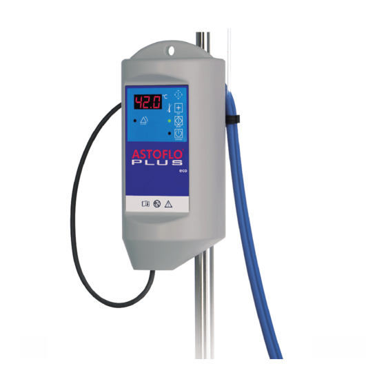
Page 19: Components Of The Astoflo Plus Eco
6 Product description ASTOFLO PLUS ECO Instructions for Use 6.3 Components of the ASTOFLO PLUS ECO Fig. 4 ASTOFLO PLUS ECO front # Part Description For adapting the attachment device to infusion Screw with Star Grip stands of different diameters. - Page 20 ASTOFLO PLUS ECO Instructions for Use 6 Product description Fig. 5 ASTOFLO PLUS ECO back Part Description Universal Attachment For secure attachment of the control unit. Device Clip for Heating Profile Fixes the heating profile/infusion line. Protects the device against accidental detaching from Knurled screw the medical rail.
-
Page 21: Control Panel
6 Product description ASTOFLO PLUS ECO Instructions for Use 6.4 Control panel Fig. 6 Control panel # Item Description 1 “Standby” LED Illuminates when the device is in Standby Mode. Press to switch from any Mode to Standby Mode. Press to switch from Standby Mode to On Mode. - Page 22 ASTOFLO PLUS ECO Instructions for Use 6 Product description # Item Description Turns on and the acoustic alarm beeps automatically if 5 “Alarm” LED an alarm condition exists. Press briefly to indicate the actual set temperature. Press several more times to select a set temperature when the device is in On Mode or in Heating Mode.
-
Page 23: Operating States
7 Operating states ASTOFLO PLUS ECO Instructions for Use 7 Operating states 7.1 Standby mode Control panel When the mains cable is plugged into the socket, the device is in Standby Mode. Action Alternately, press the “Standby” button to switch the device from any Mode to Standby Mode. - Page 24 ASTOFLO PLUS ECO Instructions for Use 7 Operating states 7.2 On mode Control panel Press the “Standby” button to switch the device from Action Standby Mode to On Mode. The “Standby” LED turns off. The device performs a self-test. All segments of the...
-
Page 25: Heating Mode
7 Operating states ASTOFLO PLUS ECO Instructions for Use 7.3 Heating mode Control panel Press the “Start” button to switch the device from On Action Mode to Heating Mode to start the heating of the heating profile. “Start LED”... -
Page 26: Increasing/Decreasing The Set Temperature Of The Heating Profile
ASTOFLO PLUS ECO Instructions for Use 7 Operating states 7.4 Increasing/Decreasing the set temperature of the heating profile Control panel 1. Press the “Set” button while the control unit is turned on (On Mode) or started (Heating Mode). 2. While the display is flashing, you can select any set temperature between 33.0°C and 43.0°C in 1°C increments... -
Page 27: Changing The Brightness Of The Display
7 Operating states ASTOFLO PLUS ECO Instructions for Use 7.5 Changing the brightness of the display Control panel 1. Press the “Test” button and “Set” button shortly at the same time while the control unit is turned on (On Mode) or started (Heating Mode). -
Page 28: Installation
ASTOFLO PLUS ECO Instructions for Use 8 Installation 8 Installation 8.1 Initial start-up Prior to first use, perform the following inspections: Visual inspection (chapter 12.1 Recurrent tests). Check the mains voltage (compare the details on the type label with the available mains voltage.) An incorrect mains voltage may destroy the... -
Page 29: Getting Started
- Damaged or missing markings/safety signs/warnings on the control unit and/or heating profile. Use of the ASTOFLO PLUS ECO must be carried out under the supervision of a physician. The mains cable should not touch the patient and should not hinder the treating personnel. - Page 30 6. Press the “Set” button to select another set temperature if needed. 7. Press the “Start” button to switch the ASTOFLO PLUS ECO to Heating Mode (“Start” LED illuminates). As long as the temperature of the heating profile is below 18 °C, the display indicates low by displaying “L”.
-
Page 31: Priming, Inserting The Infusion Line And Starting The Infusion
The temperature control of the ASTOFLO PLUS ECO controls and monitors the temperature of the heating profile, but not the patient’s body temperature. If the ASTOFLO PLUS ECO cannot be started or if the patient's temperature balance is insufficient, consider the use of alternative warming methods in... - Page 32 ASTOFLO PLUS ECO Instructions for Use 9 Getting started 1. Prime the infusion line before or after inserting into the heating profile: Allow fluid to flow until no air is observed in the infusion line and the line is primed with fluid.
-
Page 33: After Use
(all indicators turn off, the “Standby” LED turns on). To disconnect ASTOFLO PLUS ECO from the mains, it is necessary to completely pull out the plug. 3. Disconnect the infusion line from the cannula and simply pull the infusion line out of the ASTOFLO PLUS ECO heating profile. -
Page 34: Cleaning And Disinfecting
ASTOFLO PLUS ECO Instructions for Use 9 Getting started WARNING Risk of infection! Carefully clean and thoroughly disinfect the device after every use and before returning it for any repairs. NOTICE To avoid damaging during storage, place the heating profile loosely around the control unit and do not kink or clamp it. - Page 35 9 Getting started ASTOFLO PLUS ECO Instructions for Use Control Unit Clean and wipe-disinfect the control unit in accordance with the procedure below: 1. Disconnect the mains plug from the socket. 2. Clean all surfaces including with a soft cloth/cotton swab and mild soap-and- water solution.
-
Page 36: Alarms And Troubleshooting
Thus, the overheating of the heated liquid is surely prevented. ASTOFLO PLUS ECO does not require continuous supervision by the operator, but must be inspected at regular intervals (depending on the condition of the patient). -
Page 37: Low Temperature Alarm
10 Alarms and troubleshooting ASTOFLO PLUS ECO Instructions for Use 10.1 Low temperature alarm Control panel This alarm is signaled with a 10 minute delay. Then the display alternately indicates the current temperature and the symbol LO after 10 minutes. -
Page 38: Overheating Alarm
In order to prevent potential overheating due to a possible failure of the temperature control system, the ASTOFLO PLUS ECO possesses two independ- ent excessive temperature cut offs. If the blood return line is pulled out of the ASTOFLO PLUS ECO heating profile during use, the overheat- ing alarm might be activated. -
Page 39: Cable Break Alarm
10 Alarms and troubleshooting ASTOFLO PLUS ECO Instructions for Use 10.3 Cable break alarm Control panel The display indicates the symbol C. The “Start” LED flashes. The “Alarm” LED turns on. Device response There is a brief acoustic alarm signal every 16 seconds. -
Page 40: Self-Test Alarm
ASTOFLO PLUS ECO Instructions for Use 10 Alarms and troubleshooting 10.4 Self-test alarm Control panel The display indicates E. The “Alarm” LED turns on. Device response There is a brief acoustic alarm signal every 16 seconds. The control unit cannot be started. -
Page 41: Connection Alarm
10 Alarms and troubleshooting ASTOFLO PLUS ECO Instructions for Use 10.5 Connection alarm Control panel The display indicates C0. The “Start” LED flashes. Device response The “Alarm” LED turns on. There is a brief acoustic alarm signal every 16 seconds. -
Page 42: Standby Mode - Failure
ASTOFLO PLUS ECO Instructions for Use 10 Alarms and troubleshooting 10.6 Standby mode - failure Control panel The “Standby” LED LED is off, and the device Device response cannot be switched to On Mode by pressing the “Standby” button Power supply problem or no power. -
Page 43: Brief Overview Of Operating States And Alarms
11 Brief overview of operating states and alarms ASTOFLO PLUS ECO Instructions for Use 11 Brief overview of operating states and alarms 11.1 Overview of operation states “Standby“ “Start“ “Alarm“ Acoustic (blue) (green) (yellow) Display Operating alarm Possible state signal... -
Page 44: Overview Of Alarms
ASTOFLO PLUS ECO Instructions for Use 11 Brief overview of operating states and alarms 11.2 Overview of alarms “Standby“ “Start“ “Alarm“ Acoustic (blue) (green) (yellow) Display alarm Possible signal Alarm reason(s) temperature of the heating Temperature Beeps profile for longer... -
Page 45: Maintenance
12.1 Recurrent tests 12.1.1 Control unit (Heating profile see 12.1.2) A recurrent test must be carried out on the ASTOFLO PLUS ECO control unit at least every 12 months to ensure the safe operation of the warmer. Please ensure that all the applicable national directives (e.g. IEC/EN 62353) for checking the safety of medical equipment are observed additionally and that the test equipment is calibrated. - Page 46 ASTOFLO PLUS ECO Instructions for Use 12 Maintenance Test 1 Visual inspection Check the following items: Required Actions Complete and legible labeling. No damage to the housing. Front panel in good condition. (Since the front panel prevents fluid from entering the unit, it is important that its full surface adheres securely to the housing.)
- Page 47 12 Maintenance ASTOFLO PLUS ECO Instructions for Use Test 4.1 Applied part leakage current (direct method) Optional to test 4.2 Measure the maximum patient leakage current. Measure all Required combinations of line polarity with neutral open or PE open (single Actions fault condition) as well as closed (normal condition).
- Page 48 ASTOFLO PLUS ECO Instructions for Use 12 Maintenance Test 5 Manual excessive temperature cut off 1. Connect the heating profile. Required Actions 2. Press and hold the “Test” button continuously for at least 2 seconds while the device is started (Heating Mode).
- Page 49 12 Maintenance ASTOFLO PLUS ECO Instructions for Use The test is not successful if any of the following conditions occurs: The displayed temperature does not rise. The display does not indicate C0. The “Start” LED does not flash.
- Page 50 ASTOFLO PLUS ECO Instructions for Use 12 Maintenance Test 8 Temperature sensors of heating profile Preparation The safe operation of the unit depends on the accuracy of the temperature sensors. The 2 sensors can be tested by a comparison of...
- Page 51 12 Maintenance ASTOFLO PLUS ECO Instructions for Use 7. Compare the displayed temperatures of both temperature sensors with the room temperature. 8. Press the “Standby” button (Standby Mode). This test is successful when all 3 temperatures are in the range of Result 1.2°C (chapter...
-
Page 52: Set Up For Electrical Safety Tests
ASTOFLO PLUS ECO Instructions for Use 12 Maintenance 12.2 Set up for electrical safety tests For measuring the protective earth resistance, the equipment/earth leakage cur- rent and the applied part leakage current the following test set up can be used:... -
Page 53: Test Protocol
12 Maintenance ASTOFLO PLUS ECO Instructions for Use 12.3 Test protocol Control unit Heating profile Test equipment Type Type Date of calibration Test 1: Visual inspection control unit Type plate on control unit Front panel Housing Attachment device Power supply cord Test 2: Protective earth resistance Value [Ω]... - Page 54 ASTOFLO PLUS ECO Instructions for Use 12 Maintenance Test 4.2: Applied part leakage current (alternative method) Optional to test 4.1 Min [mA] Value [mA] Max [mA] P/F Applied part leakage current 0.005 0.05 Manual tests Test 5: Manual excessive temperature cut off Test (E11, E12)
-
Page 55: Technical Data
13 Technical data ASTOFLO PLUS ECO Instructions for Use 13 Technical data ASTOFLO PLUS ECO ..EU AFP300..CH ..UK ..NA AFP302..DK ..AU ..CN Electrical connection 115 VAC 230 VAC 240 VAC 50 – 60 Hz 50 – 60 Hz... -
Page 56: Conformity With International Standards
ASTOFLO PLUS ECO Instructions for Use 14 Conformity with international standards 14 Conformity with international standards Standard Title IEC/EN 60601-1 Medical electrical equipment - Part 1: ANSI/AAMI ES 60601-1 General requirements for basic safety and essential CAN/CSA C22.2 No. performance... -
Page 57: Ordering Information And Accessories
15 Ordering information and accessories ASTOFLO PLUS ECO Instructions for Use 15 Ordering information and accessories ASTOFLO PLUS ECO Warmer consists of a control unit and one heating profile, you can order these according the following order numbers: Description (Order No.) -
Page 58: Guidelines And Manufacturer's Declaration
Guidance and manufacturer's declaration - electromagnetic emissions The ASTOFLO PLUS ECO is intended for use in the electromagnetic environment specified below. The customer or user of the ASTOFLO PLUS ECO should assure that it is used in such an environment. Emission test... - Page 59 Guidance and manufacturer's declaration - electromagnetic immunity The ASTOFLO PLUS ECO is intended for use in the electromagnetic environment specified below. The customer or user of the ASTOFLO PLUS ECO should assure that it is used in such an environment. Electromagnetic environment – guidance...
Need help?
Do you have a question about the ASTOFLO PLUS ECO and is the answer not in the manual?
Questions and answers