Advertisement
Quick Links
Advertisement

Subscribe to Our Youtube Channel
Related Manuals for SMA EV Charger 7.4


Summary of Contents for SMA EV Charger 7.4
- Page 1 Operating manual SMA EV CHARGER ENGLISH EVCxx-10-BE-en-10 | Version 1.0...
- Page 2 SMA Solar Technology AG Legal Provisions The information contained in these documents is the property of SMA Solar Technology AG. No part of this document may be reproduced, stored in a retrieval system, or transmitted, in any form or by any means, be it electronic, mechanical, photographic, magnetic or otherwise, without the prior written permission of SMA Solar Technology AG.
- Page 3 SMA Solar Technology AG Table of Contents Table of Contents Information on this Document..........Validity ........................Target Group......................Content and Structure of this Document ..............Levels of Warning Messages ..................Symbols in the Document ..................Typographical Elements in the Document ..............
- Page 4 Table of Contents SMA Solar Technology AG Commissioning ................. 34 Commissioning Procedure ..................34 Commissioning the Product ..................34 Changing the Network Configuration ..............36 Configuring the Product ..................... 36 Operation ................. 38 Establishing a connection to the user interface ............38 8.1.1...
- Page 5 You will find the latest version of this document and further information on the product in PDF format and as eManual at www.SMA-Solar.com. You can also call up the eManual via the user interface of the product. Illustrations in this document are reduced to the essential information and may deviate from the real product.
- Page 6 1 Information on this Document SMA Solar Technology AG NOTICE Indicates a situation which, if not avoided, can result in property damage. Symbols in the Document Symbol Explanation Information that is important for a specific topic or goal, but is not safety-rele-...
- Page 7 All components must remain within their permitted operating ranges and their installation requirements at all times. The product must only be used in countries for which it is approved or released by SMA Solar Technology AG and the grid operator.
- Page 8 2 Safety SMA Solar Technology AG DANGER Danger to life due to electric shock in case of overvoltages and if surge protection is missing Overvoltages (e. g. in the event of a flash of lightning) can be further conducted into the building and to other connected devices in the same network via the network cables or other data cables if there is no surge protection.
- Page 9 Sunny Portal or the use of FTP push. High costs for the Internet connection can be the result. • SMA Solar Technology AG recommends using an Internet flat rate. NOTICE Damage to the product due to cleaning agents The use of cleaning agents may cause damage to the product and its components.
- Page 10 3 Scope of Delivery SMA Solar Technology AG Scope of Delivery Check the scope of delivery for completeness and any externally visible damage. Contact your distributor if the scope of delivery is incomplete or damaged. Figure 1: Components included in the scope of delivery...
- Page 11 SMA Solar Technology AG 3 Scope of Delivery Position Quantity Designation 5-pole terminal block for connecting a signal source to the digital in- Quick Reference Guide Operating manual EVCxx-10-BE-en-10...
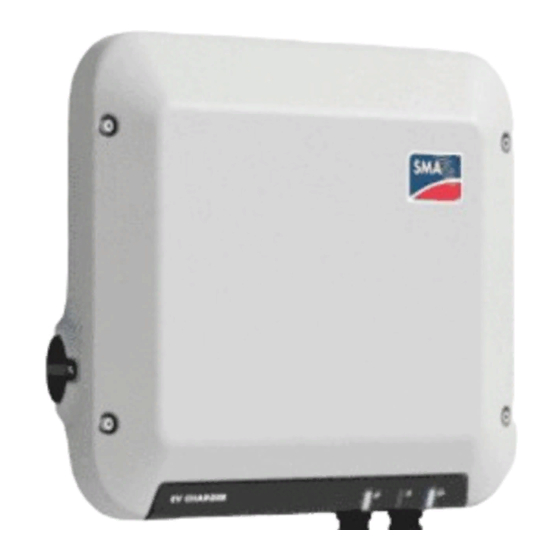
- Page 12 4 Product Overview SMA Solar Technology AG Product Overview Product Description Figure 2: Design of the product Position Designation Rotary switch to select charging mode Terminal cover Cable glands for the charging cable, the AC cable, the network cable and the signal source cable for the digital input LEDs The LEDs indicate the operating state of the product.
- Page 13 4 Product Overview Position Designation Label with QR Code for scanning via the SMA 360° App and easy con- nection to the inverter's user interface via WLAN Type label The type label clearly identifies the product. The type label must remain permanently attached to the product.
- Page 14 4 Product Overview SMA Solar Technology AG Symbol Explanation Fast charging This symbol is located on the rotary switch and indicates the switch position for fast charging. Smart charging This symbol is located on the rotary switch and indicates the switch position for charging controlled by the energy management system.
- Page 15 There is a QR code on the product by default. By scanning the QR Code attached to the product via the SMA 360° app or SMA Energy app, access to the product is established via Wi-Fi and the connection to the user interface is made automatically.
- Page 16 4 Product Overview SMA Solar Technology AG LED signal Explanation The green LED is glowing Charge mode The EV Charger charges the vehicle at more than 90% of its nominal power. The green LED is pulsing Charge mode The EV Charger is equipped with a dynamic power display via the green LED.
- Page 17 SMA Solar Technology AG 4 Product Overview System Overview SUNNY PORTAL UTILITY GRID Solar energy Alternating current Communication CUSTOMER SYSTEM SUNNY HOME MANAGER 2.0 SMA PV SYSTEM CHARGING SYSTEM SMA STORAGE SYSTEM Figure 3: Design of the system Operating manual...
- Page 18 4 Product Overview SMA Solar Technology AG 4.5.1 Circuitry Overview DISTRIBUTION BOARD SUNNY HOME MANAGER 2.0 GRID-CONNECTION POINT with energy meter of the grid operator PROTECTIVE DEVICES max. 63 A with RCD and LSS max. max. 16 A 50 A max.
- Page 19 SMA Solar Technology AG 4 Product Overview 4.5.2 Communication Overview SMA APPs SUNNY PORTAL GRID OPERATOR Public Internet Ethernet LAN Ripple control signal Digital signal Radio INTERNET SUNNY BOY ROUTER SUNNY RIPPLE CONTROL HOME MANAGER 2.0 SWITCH RECEIVER SUNNY BOY...
- Page 20 5 Mounting SMA Solar Technology AG Mounting Requirements for Mounting Requirements for mounting location: WARNING Danger to life due to fire or explosion Despite careful construction, electrical devices can cause fires. This can result in death or serious injury. • Do not mount the product in areas containing highly flammable materials or gases.
- Page 21 SMA Solar Technology AG 5 Mounting 15° Figure 6: Permitted and prohibited mounting positions Dimensions for mounting: Figure 7: Position of the anchoring points(Dimensions in mm) Recommended clearances: If you maintain the recommended clearances, adequate heat dissipation will be ensured. Thus, you will prevent power reduction due to excessive temperature.
- Page 22 5 Mounting SMA Solar Technology AG Figure 8: Recommended clearances(Dimensions in mm) Mounting the product Additionally required material (not included in the scope of delivery): • 3 stainless steel hexagon head wood screws (AF 10, diameter 6 mm), screw length must be suitable for the support surface and the weight of the product (fastening bracket thickness: 4 mm)
- Page 23 SMA Solar Technology AG 5 Mounting 5. Insert the screws until there is at least 6 mm clearance between the screw head and the support surface. 6. Remove the brown adhesive tape from the product. 7. Attach the mounting bracket with conical spring washer and hexagon socket cap head screw to the product (torque: 6 Nm ±...
- Page 24 5 Mounting SMA Solar Technology AG 10. Tighten the screws hand-tight using a ratchet or box wrench. When doing this you can compensate for any misalignment of the drill holes by aligning the metal brackets accordingly. 11. Ensure that the product is securely in place.
- Page 25 SMA Solar Technology AG 6 Electrical Connection Electrical Connection Overview of the Connection Area 6.1.1 View from Below Figure 9: Bottom view of product with attached terminal cover Position Designation Enclosure opening for cable gland M25 for the connection of a signal source...
- Page 26 6 Electrical Connection SMA Solar Technology AG Mounting the Connection Cap Requirements: ☐ Only use the supplied cable glands. Procedure: 1. Attach the cable gland for connecting the utility grid to the terminal cover: • If the AC cable has a diameter of 11 mm to 17 mm, insert the M25 cable gland into the opening of the terminal cover and tighten.
- Page 27 SMA Solar Technology AG 6 Electrical Connection AC Connection 6.3.1 Connecting the Utility Grid AC cable requirements as follows: ☐ The maximum permitted temperature of the terminal block for AC connection of 105°C must be observed. ☐ External diameter: 11 mm to 21 mm ☐...
- Page 28 6 Electrical Connection SMA Solar Technology AG 6.3.2 Connecting Additional Grounding If additional grounding or equipotential bonding is required locally, you can connect additional grounding to the product. This prevents touch current if the grounding conductor at the terminal for the AC cable fails.
- Page 29 SMA Solar Technology AG 6 Electrical Connection Connecting the Charging Cable Requirements: ☐ Only use the supplied charging cable. ☐ Do not use adapters or extensions for the charging cable. Procedure: 1. Disconnect the product from voltage sources (see Section 9, page 45).
- Page 30 6 Electrical Connection SMA Solar Technology AG Additionally required material (not included in the scope of delivery): ☐ Bootlace ferrules (if necessary) Requirements: ☐ The signal source must be technically suitable for connection to the digital inputs (see Section 14, page 59).
- Page 31 SMA Solar Technology AG 6 Electrical Connection Procedure: 1. Disconnect the product from voltage sources (see Section 9, page 45). 2. Connect the connection cable to the digital signal source (see the manual from manufacturer). 3. Dismantle the connection cable 150 mm. 4. Strip off the insulation of required conductors by 6 mm.
- Page 32 6 Electrical Connection SMA Solar Technology AG Connecting the Network Cables DANGER Danger to life due to electric shock in case of overvoltages and if surge protection is missing Overvoltages (e. g. in the event of a flash of lightning) can be further conducted into the building and to other connected devices in the same network via the network cables or other data cables if there is no surge protection.
- Page 33 SMA Solar Technology AG 6 Electrical Connection 3. Press the cable support sleeve out of the threaded sleeve. 4. Feed the network cable through the swivel nut and threaded sleeve. Attach the cable support sleeve to the network cable. 5. Press the cable support sleeve into the threaded sleeve.
- Page 34 • Connection via Ethernet in the local network Change the network configuration, if necessary. The auto- Section 7.3, page 36 matic network configuration recommended by SMA Solar Technology AG via DHCP server is activated by default. Carry out the configuration using the installation assistant. Section 7.4, page 36 To monitor the system in the Sunny Portal and view the https://www.sunnypor-...
- Page 35 9. In fast charging mode, perform the test of the charging station according to IEC 61851 and fill in the test report. An example of a test report can be found at www.SMA-Solar.com. 10. If necessary, rectify any defects found.
- Page 36 On the welcome page, you can change the network configuration. The automatic network configuration recommended by SMA Solar Technology AG via DHCP server is activated by default. Only change the network configurations if the default configuration is not suitable for your network.
- Page 37 SMA Solar Technology AG 7 Commissioning If you click on [Next], the commissioning assistant starts. With the commissioning assistant, you can create an administrator account to access and configure the product. Procedure: 1. Click on [Next] on the welcome page.
- Page 38 ☐ An user account for Sunny Portal must already exist. Procedure: 1. Open the SMA 360° App and login with dem Sunny Portal account details. 2. Select QR-Code Scan in the menu. 3. Scan the QR Code on you product via the SMA 360° App.
- Page 39 Connection with Wi-Fi network search 1. Search for Wi-Fi networks with your end device. 2. Select the SSID of the product SMA[serial number] in the list with the detected Wi-Fi networks. 3. Enter the device-specific Wi-Fi password (see WPA2-PSK on the type label).
- Page 40 Web browser signals a security vulnerability After the IP address has been entered, a message might appear indicating that the connection to the user interface of the product is not secure. SMA Solar Technology AG guarantees the security of the user interface.
- Page 41 SMA Solar Technology AG 8 Operation Procedure: • Enter the IP address of the product in the address bar of the web browser. ☑ The login page of the user interface opens. Design of the User Interface Figure 13: Design of the user interface (example)
- Page 42 8 Operation SMA Solar Technology AG Position Designation Description Monitoring Displays depending on the selected device the following information on the current level and the superior levels: • Energy and power • Instantaneous values • Status list • Event monitor...
- Page 43 The EV Charger is operated as a necessary appliance with as much surplus PV en- ergy as possible. By entering a departure time and an amount of energy to be charged in the SMA Energy App, the Sunny Home Manager intelligently plans the charging process. The Sunny Home Manager enables charging at minimum cost and with maximum utilization of PV power with sufficient charging to reach the des- tination at the entered departure time.
- Page 44 Switching between smart charging - PV surplus charging and smart charging - forecast-based charging 1. Open the SMA Energy app. 2. Select [eMobility] in the lower bar. ☑ Information on the current charging mode is displayed.
- Page 45 SMA Solar Technology AG 9 Disconnecting the product from voltage sources Disconnecting the product from voltage sources Prior to performing any work on the product, always disconnect it from all voltage sources as described in this section. Always adhere to the prescribed sequence.
- Page 46 9 Disconnecting the product from voltage sources SMA Solar Technology AG 5. For EVC22-3AC-10, check that there is no voltage EVC22-3AC-10 between L1 and grounding conductor, L2 and L 1 L 2 grounding conductor and L3 and grounding conductor at the terminal block for connecting the utility grid.
- Page 47 SMA Solar Technology AG 10 Clean the product 10 Clean the product NOTICE Damage to the product due to cleaning agents The use of cleaning agents may cause damage to the product and its components. • Clean the product and all its components only with a cloth moistened with clear water.
- Page 48 11 Troubleshooting SMA Solar Technology AG 11 Troubleshooting 11.1 Resetting the Administrator Account If you have forgotten the administrator password for the product, you can reset the administrator account with a device key (DEV KEY) and then assign a new password.
- Page 49 SMA Solar Technology AG 11 Troubleshooting Event number Message, cause and corrective measures 6501 Self-diagnosis > The internal temperature exceeds a permissible maxi- mum value The product has switched off because the internal temperature is above the maximum permissible value.
- Page 50 11 Troubleshooting SMA Solar Technology AG Event number Message, cause and corrective measures 7330 Condition test failed The testing of the update conditions was not successful. The firmware update package is not suitable for this product. Corrective measures: • Retry update.
- Page 51 SMA Solar Technology AG 11 Troubleshooting Event number Message, cause and corrective measures 9801 Vehicle not compatible The vehicle is not suited for use with the EV Charger. Corrective measures: • Ensure that the vehicle is suited for use with the EV Charger.
- Page 52 11 Troubleshooting SMA Solar Technology AG Event number Message, cause and corrective measures 10107 Update failed The update was not carried out successfully. Corrective measures: • Retry update. • If this message is displayed again, contact the Service. 10111 Update successful The firmware update was completed successfully.
- Page 53 SMA Solar Technology AG 11 Troubleshooting Event number Message, cause and corrective measures 10286 Wi-Fi connection lost The product has lost Wi-Fi connection to the selected network. Corrective measures: • Ensure that the Wi-Fi router or WLAN access point is still active.
- Page 54 12 Decommissioning the Product SMA Solar Technology AG 12 Decommissioning the Product To decommission the product completely upon completion of its service life, proceed as described in this Section. CAUTION Risk of injury due to weight of product Injuries may result if the product is lifted incorrectly or dropped while being transported or mounted.
- Page 55 SMA Solar Technology AG 12 Decommissioning the Product 6. Take the cable support sleeve out of the threaded sleeve and remove the cable support sleeve from the network cable. 7. Lead the network cable out of the threaded sleeve and the swivel nut.
- Page 56 12 Decommissioning the Product SMA Solar Technology AG 13. Lead the AC cable out of the product through the cable gland. If necessary, loosen the swivel nut of the cable gland. 14. With EVC22-3AC-10, remove the conductors L1, L2, EVC22-3AC-10...
- Page 57 SMA Solar Technology AG 12 Decommissioning the Product 19. Remove the product with the metal brackets from the screws. 20. If the product is to be stored or shipped, pack the product. Use the original packaging or packaging that is suitable for the weight and size of the product.
- Page 58 7. If the defective product had been registered by a communication product, replace it with the new product in the communication product (see operating manual of communication product). 8. Pack the defective product in the packaging of the replacement device and arrange with SMA Solar Technology AG for it to be picked up.
- Page 59 SMA Solar Technology AG 14 Technical Data 14 Technical Data Inputs and outputs (AC) EVC7.4-1AC-10 EVC22-3AC-10 Charging capacity, freely ad- 1300 W to 7400 W 1300 W to 22000 W justable (Mode 3) Nominal voltage 230 V 400 V Rated frequency 50 Hz 50 Hz Nominal current, single-phase 32 A...
- Page 60 14 Technical Data SMA Solar Technology AG Maximum data volume per charging station with 550 MB/month Speedwire Wi-Fi range in free-field conditions 100 m Quantity maximum detectable Wi-Fi networks Cooling method Convection Degree of protection in accordance with IP65 IEC 60529 Impact resistance IK08 Protection class in accordance with IEC 61140...
- Page 61 SMA Solar Technology AG 15 Contact 15 Contact If you have technical problems with our products, please contact the SMA Service Line. The following data is required in order to provide you with the necessary assistance: • Device type • Serial number •...
- Page 62 Toll free for Australia: SMA Online Service Center: 1800 SMA AUS www.SMA-Service.com (1800 762 287) International: +61 2 9491 4200 United Arab SMA Middle East LLC India SMA Solar India Pvt. Ltd. Emirates Abu Dhabi Mumbai +971 2234 6177 +91 22 61713888 SMA Online Service Center: www.SMA-Service.com EVCxx-10-BE-en-10 Operating manual...
- Page 63 SMA Solar Technology AG 15 Contact ไทย Service Partner for String inverter: 대한민국 Enerone Technology Co., Ltd Solar Power Engineering Co., Ltd. 4th Fl, Jungbu Bldg, 329, 333/7,8,9 United Tower Build- Yeongdong-daero, Gangnam- ing 4th floor. Soi Sukhumvit 55 (Thonglor 17),...
- Page 64 (L 174/88, June 8, 2011) and 2015/863/EU (L 137/10, March 31, 2015) (RoHS) SMA Solar Technology AG confirms herewith that the products described in this document are in compliance with the fundamental requirements and other relevant provisions of the above- mentioned directives. The entire EU Declaration of Conformity can be found at www.SMA- Solar.com.
- Page 66 www.SMA-Solar.com...
Need help?
Do you have a question about the EV Charger 7.4 and is the answer not in the manual?
Questions and answers