
Summary of Contents for MacDon B6604
- Page 1 A40DX and A40DX Grass Seed Auger Header Reel Speed Control Kit (MD #B6604 and 318001) Installation Instructions 214679 Revision B Original Instruction The harvesting specialists.
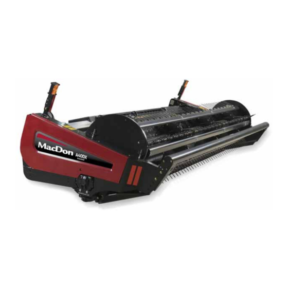
- Page 2 A40DX Grass Seed (GSS) Auger Header Published July 2018...
- Page 3 Introduction The Auger Header Reel Speed Control kit (MD #B6604 or 318001) is required to provide the variable reel speed function on the A40DX and A40DX Grass Seed (GSS) Header. This document explains how to install the kit. A list of parts included in this kit is provided in Chapter...
- Page 4 List of Revisions At MacDon, we’re continuously making improvements, and occasionally these improvements affect product documentation. The following list provides an account of major changes from the previous version of this document. Summary of Change Location • Front cover Added kit MD #318001.
-
Page 5: Table Of Contents
TABLE OF CONTENTS Introduction..............................i List of Revisions ............................ii Chapter 1: Safety ............................ 1 1.1 Signal Words ............................1 1.2 General Safety.............................2 Chapter 2: Parts List ..........................5 Chapter 3: Installation Instructions ....................7 Chapter 4: Operation ........................... 13 214679 Revision B... -
Page 7: Chapter 1: Safety
1 Safety 1.1 Signal Words Three signal words, DANGER, WARNING, and CAUTION, are used to alert you to hazardous situations. Signal words are selected using the following guidelines: DANGER Indicates an imminently hazardous situation that, if not avoided, will result in death or serious injury. WARNING Indicates a potentially hazardous situation that, if not avoided, could result in death or serious injury. -
Page 8: General Safety
SAFETY 1.2 General Safety CAUTION The following are general farm safety precautions that should be part of your operating procedure for all types of machinery. Protect yourself. • When assembling, operating, and servicing machinery, wear all protective clothing and personal safety devices that could be necessary for job at hand. - Page 9 SAFETY • Wear close-fitting clothing and cover long hair. Never wear dangling items such as scarves or bracelets. • Keep all shields in place. NEVER alter or remove safety equipment. Make sure driveline guards can rotate independently of shaft and can telescope freely. •...
-
Page 11: Chapter 2: Parts List
2 Parts List Part Number Description Quantity BRACKET – BAR 170974 FITTING – ELBOW HYDRAULIC 252896 VALVE – FLOW CONTROL 170955 FITTING – ELBOW 90° HYDRAULIC 135918 FITTING – ELBOW 90° HYDRAULIC 136089 FITTING – TEE HYDRAULIC 135784 HOSE – HYDRAULIC 170952 HARNESS –... -
Page 13: Chapter 3: Installation Instructions
3 Installation Instructions To install the Reel Speed Control kit (MD #B6604 or 318001) on an A40DX or A40DX Grass Seed Auger Header, follow this procedure: CAUTION Ensure shield lock engages in the open position as shown at location (B) before letting go of shield. - Page 14 INSTALLATION INSTRUCTIONS Relocating knife guard straightening tool 5. Remove hair pin (A) securing knife guard straightening tool (B) in its storage position, then remove tool (B). Retain for reinstallation. 6. Remove bolt and nut securing wrench support plate (C) to the bar (D). Retain for reinstallation. Figure 3.3: Knife Guard Straightening Tool in Storage Position (with Existing Bracket) 7.
- Page 15 INSTALLATION INSTRUCTIONS Installation of reel speed hydraulic valve 10. Loosely install elbow fitting (B) (MD #252896) in port EF of flow control valve (C) (MD #170955). IMPORTANT: Orient the fittings on the valve as shown. 11. Loosely install 90-degree elbow fitting (A) (MD #136089) in port IN.
- Page 16 INSTALLATION INSTRUCTIONS 14. Position flow control valve assembly (A) as shown. 15. Loosely connect elbow fitting (B) in port EF of flow control valve (A) to the elbow fitting (C) of reel motor (D). 16. Loosely connect the hydraulic hose (E) that is routed through the endshield to elbow fitting (F) in port IN of flow control valve (A).
- Page 17 INSTALLATION INSTRUCTIONS 20. Secure the two hydraulic hoses (A) using two clamps (B) (MD #135235), bolt (C) (MD #21264), and nut (D) (MD #30228). 21. Tighten all fittings. Figure 3.12: Securing Hoses with Clamps 22. Route reel speed harness (A) (MD #283709) along the main header harness using a dual swivel spacer (MD #134442) and two cable ties (MD #30753) as required to keep the harness secured.
- Page 18 INSTALLATION INSTRUCTIONS 26. Non-Grass Seed Headers only: Lower shield (B). 27. Non-Grass Seed Headers only: Engage rubber latch (A). Figure 3.15: Closing Driveline Shield 28. Grasp endshield at top, push slightly, and move support (A) inboard to disengage. 29. Lower endshield to about 30 cm (1 ft.) from closed position.
-
Page 19: Chapter 4: Operation
4 Operation Installation of this kit requires the following software versions installed in the windrower: • Harvest Performance Tracker (HPT) software: Install_SPW_HPAH203586K_.efs or newer • Master Controller software: MCAH203587M.ida4 or newer 1. Turn ignition ON. HPT will display auger header (A) as attached. - Page 20 OPERATION 5. Using the HPT scroll knob, scroll and select ATTACHMENTS (A). A new page opens. Figure 4.4: HPT Screen Display 6. Select DIFFERENTIAL AUGER-REEL CONTROL (A). Once this is done, the auger speed can be controlled via the quick menus on RUN SCREEN 2. NOTE: This will enable the system to use the differential auger- reel control package.
- Page 21 OPERATION 8. Press the scroll knob (A) on the HPT or the SELECT button (B) on the ground speed lever (GSL) to display the Quick Menu system. Figure 4.7: HPT Scroll Knob and GSL Select Button 9. Scroll to the auger speed tile (A) and select it. Figure 4.8: HPT Screen Display 10.
- Page 24 MacDon Industries Ltd. MacDon Brasil Agribusiness Ltda. 680 Moray Street Rua Grã Nicco, 113, sala 202, B. 02 Winnipeg, Manitoba Mossunguê, Curitiba, Paraná Canada R3J 3S3 CEP 81200-200 Brasil t. (204) 885-5590 f. (204) 832-7749 t. +55 (41) 2101-1713 f. +55 (41) 2101-1699 MacDon, Inc.
Need help?
Do you have a question about the B6604 and is the answer not in the manual?
Questions and answers