Table of Contents
Advertisement
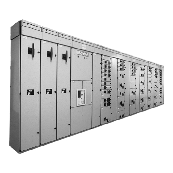
Low voltage – Distribution system & Motor Control Centre
Capitole 40
User manual 1991.901 G01 002
Operations consisting of installing, connecting, operating, checking, commissioning, decommissioning
and maintaining low-voltage switchgear of the Capitole 40 type must only be carried out by authorised
personnel.
User manual
Low voltage – Distribution
system & Motor Control Centre
Capitole 40
1991.901 G01 002
Eaton Electric B.V.
P.O.box 23, 7550 AA Hengelo, The Netherlands
tel:
+31 74 246 91 11
fax:
+31 74 246 44 44
e-mail:
holec-info@eaton.com
internet:
www.holec.com
In the event of failure
Eaton-Electrical Services & Systems : tel: +31 74 246 68 88
Advertisement
Table of Contents

Subscribe to Our Youtube Channel
Related Manuals for Eaton Holec Capitole 40


Summary of Contents for Eaton Holec Capitole 40
- Page 1 In the event of failure Eaton-Electrical Services & Systems : tel: +31 74 246 68 88 Operations consisting of installing, connecting, operating, checking, commissioning, decommissioning and maintaining low-voltage switchgear of the Capitole 40 type must only be carried out by authorised...
- Page 2 Administrative data Issue number: G01 002 Date of issue: 30-09-2008...
-
Page 3: Table Of Contents
Capitole 40 CONTENTS GENERAL ....................5 INSTRUCTION FOR USE OF MANUAL..............5 1.1.1 Aim of the manual ..................... 5 1.1.2 Structure of the manual .................... 5 DESCRIPTION OF THE CAPITOLE 40 SYSTEM ............ 6 1.2.1 General........................6 1.2.2 Characteristics of the system..................6 1.2.3 Dimensions and coding of the cubicles .............. - Page 4 Capitole 40 EXTENSION AND MODIFICATION OF LAY-OUT ..........48 3.4.1 Extension of the assembly ..................48 3.4.2 Modification of a withdrawable version of the assembly ......... 50 3.4.3 Modification of a removable version of the assembly..........63 3.4.3.1 Exchanging a plug-in unit (removable outgoing units) ..........63 3.4.3.2 Replacing the removable motor starters ..............
-
Page 5: General
1.1.1 Aim of the manual This manual contains instructions for the installation, putting into operation and use of the Eaton Holec low voltage switchgear system type Capitole 40. Instructions for trouble shooting are also given. It is important for the... -
Page 6: Description Of The Capitole 40 System
Capitole 40 1.2 DESCRIPTION OF THE CAPITOLE 40 SYSTEM 1.2.1 General The Capitole 40 system is a low voltage switch and distribution-system made up of standard sheet steel cubicles, suitable for both distribution and as a motor control centre. The system is designed for a nominal service-voltage of 690 V. -
Page 7: Dimensions And Coding Of The Cubicles
Capitole 40 1.2.3 Dimensions and coding of the cubicles Height Capitole 40 cubicles are of a modular design. The standard height is 2300 mm. A special version is available, with a height of 1925 mm. The space in which apparatus can be fitted amounts to a maximum of 2000 mm, this being equal to sixteen times the module height of 125 mm. - Page 8 Capitole 40 Width The width of the cubicles is included in the code. The code consists of two letters CT followed by a multiple of 125 mm and indicates the width of the switchgear compartment; e.g. CT 4 is a cubicle with a switchgear compartment of 4 x 125 mm = 500 mm.
-
Page 9: Standards
The system meets the highest safety-requirements and is KEMA approved. 1.2.5 Identification Order number: Serial number: Supplied by: Eaton Electric B.V. P.O. box 23, 7550 AA Hengelo, The Netherlands tel: +31 74 246 91 11 fax: +31 74 246 44 44 e-mail: holec-info@eaton.com... -
Page 10: Instructions For Installation
After unpacking check the cubicles for any possible transit- damage and/or whether any apparatus is missing. If the cubicles have been damaged during transit, contact the carrier and Eaton Holec in order to have the damage dealt with. Copper busbars, withdrawable circuit-breakers and fitting- materials are always packed separately. - Page 11 Capitole 40 Cubicle weights excluding packaging Cubicle with standard contents Cubicle with withdrawable circuit - breakers Cubicle type Weight (approx) Cubicle type Weight (approx) 130 kg CT4D 220 kg 1) CT3D 170 kg CT4D 300 kg 2) CT6DA 400 kg 3) 160 kg CT6DA 410 kg 4)
-
Page 12: Dimensions Of Installation Rooms
Capitole 40 2.1.2 Dimensions of installation rooms In order to install a switchboard, a number of conditions have to be satisfied. Therefore, the switch room has to comply with certain requirements. Height There must be a free space of 200 mm available above the switchboard, for fitting of the busbars and cable mounting. - Page 13 Capitole 40 Installation of switchboard with respect to left side plate.(CT4.2, CT4.3 EN CT4.4 ) and right side-plate wall CT2.4, CT3.4 en CT2.6 The minimum distance on the left side of the • switchboard must be 200 mm to enable the doors / covers to be opened, and on the right side of the CT2.4, CT3.4 and CT2.6 panels 100 mm This is necessary to prevent problems when...
-
Page 14: Floorplan
Capitole 40 2.1.3 Floorplan Check with Figures 2-5 to 2-9 whether the dimensions of the recesses and fixing holes in the floor have been correctly carried out. Opening for cable Entry from the bottom 1) 300 mm for cubicles with trunking Figure 2-5: Capitole 40 cubicles without rear extension and without cable compartment 1991.901 G01 002... - Page 15 Capitole 40 Opening for cable Entry from the bottom These cubicles are suitable for current transformer compartments and instrumentation compartment 1) 300 mm for cubicles with trunking Figure 2-6: Capitole 40 cubicles without rear extension and wit cable compartment 1991.901 G01 002...
- Page 16 Capitole 40 Opening for cable Entry from the bottom 1) 300 mm for cubicles with trunking Figure 2-7: Capitole 40 cubicles with rear extension 175 mm 1991.901 G01 002...
- Page 17 Capitole 40 A Opening for cable entry from the bottom B Opening for cable entry from the top 1) 300 mm for cubicles with trunking Figure 2-8: Capitole 40 cubicles with rear extension 300 mm 1991.901 G01 002...
- Page 18 Capitole 40 Remark For Capitole 40 cubicles with rear extension 450 mm see cubicles without rear extension in Figures 2-6 and 2-7. The dimensions in question ought to be included twice when calculating the depth. A Opening for cable entry from the bottom B Opening for cable entry from the top 1) 300 mm for cubicles with trunking Figure 2-9: Capitole 40 cubicles of 750 mm depth for the purposes of rear connection...
-
Page 19: Erecting The Unit
Before installation of the assembly is started, it must be ascertained whether the floor on the site is flat and level. If an Eaton Holec foundation-frame is used this must be made level by means of metal propping material If the assembly is to be installed without a foundation- frame, the highest points of the floor must be located. - Page 20 Capitole 40 ASSEMBLY OF A CORNER CUBICLE If one or more corner cubicles are to be assembled, the following components are required : busbar • front - plate • associated fixing materials • A CORNER PANEL (FRONT SIDE AT 90° TO EACH OTHER) SHOULD BE ASSEMBLED AS FOLLOWS: Mount the front-plate with supporting-strip, pos.
-
Page 21: Fitting The Busbar Systems
Capitole 40 The cubicle which has not yet been put into place, pos. • 4, is attached to the front-plate from the inside using four hexagonal bolts M8x20. Finally, the cubicle, pos. 4, is attached to the busbar duct, also from the inside, using one hexagonal bolt M8x20, see Figure 2-14. - Page 22 Capitole 40 In order to attach the earth busbar, the following is necessary (see Figure 2-18) - one clamp-plate - two hexagonal bolts M6x30 Figure 2-18: Clamp plate For the fitting of the earth busbar in a cubicle, see Figure 2-19) Figure 2-19: Fitting In order to make a tee-off from the horizontal earth busbar in the busbar compartment to the vertical busbar (see...
-
Page 23: Auxiliary Busbars Respectively Auxiliary Wiring
Capitole 40 If the earth busbar has to be coupled to another, this ought to be carried out as follows: Coupling always take place at the partition of two • cubicles. A butt joint is made between the two busbar ends. •... - Page 24 Capitole 40 busbars into the pre-fitted auxiliary busbar holders. Auxiliary busbars resp. auxiliary wiring in the duct Replace the cover. If there is insufficient room on the left or at the front of the cubicle right hand side of the unit, the busbar holders should be The auxiliary busbars are supplied separately in lengths of removed for a length of 1.90 m.
-
Page 25: Placing The Main Busbars
Capitole 40 The inter-connections are made using a screwdriver, see Figure 2-27. 2.2.2.4 Placing the main busbars The main busbars are placed in the busbar compartment in the upper part of the assembly. Remove the top half of the busbar supports. •... - Page 26 Capitole 40 Busbar support for one busbar per phase The following figures show the position of the busbar supports for one busbar per phase, for the various cubicles. see remark see remark Figure 2-30: Cubicle CT4 EMARK see remark The arrow indicates the place where the busbars are normally connected in the assembly and also the place where the busbars end in the right-hand cubicle.
- Page 27 Capitole 40 see remark Note: From may 1997, all busbar connections will be located at the intersection of two panels when extentions are carried out, (see Figure 2-41 en 2-28) Figure 2-33: Cubicle CT4.3 see remark Note: From May 1997, all busbar connections will be located at the intersection of two panels when extentions are carried out, (seeFigure 2-41 en 2-28) Figure 2-34: Cubicle CT4.4...
- Page 28 Capitole 40 Busbar support for two busbars per phase The position of the busbar supports for parallel busbars in the various cubicles is shown in the following figures. see remark Figure 2-35: Cubicle CT4 see remark EMARK The arrow indicates the place where busbars are normally connected in the assembly and also the place where the busbars finish in the right-hand cubicle.
-
Page 29: Coupling Main Busbars
Capitole 40 see remark Figure 2-38: Cubicle CT4.3 see remark Note: From May 1997, all busbar connections will be located at the intersection of two panels when extentions are carried out, (see Figure 2-41 en 2-28). Figure 2-39: Cubicle CT4.4 2.2.2.5 Coupling main busbars Main busbars are coupled if:... - Page 30 Capitole 40 The length of the hexagonal socket-head coupling bolts M12 used to clamp the busbars together depends upon the dimensions of the busbars, as shown in the table. Main busbar Length of Torques dimensions the bolts 25 X 10 M8 X 45 35 X 10 M8 X 60...
- Page 31 Capitole 40 Epoxy resin insulated busbars Insulated busbars are supplied with bare coupling points. Coupling is carried out in a identical way to that of air insulated busbar systems (see Figure 2-40). For a single bar/phase the separately delivered dummy bar must be used (see Figure 2-47).
-
Page 32: Fitting The Main Busbars
Capitole 40 2.2.2.6 Fitting the main busbars The top half of the busbar support can now be fitted. A brass clamp-strip or a washer is fitted to the top half of the busbar support after which the top half of the busbar support is clamped to the bottom half with two hexagonal socket-head bolts M8 for each busbar support, see figure 2-48. -
Page 33: Busbar Tee-Offs
Capitole 40 2.2.2.7 Busbar tee-offs With single, air-insulated busbars Tee-off to the vertical busbars for outgoing feeders is carried out in the case of single main busbars by means of an angled clamp and a hexagonal socket-head bolt M12. The length of the bolt depends upon the dimensions of the horizontal main busbars and the thickness of the busbar tee-off. - Page 34 Capitole 40 With parallel, air-insulated busbars Tee-off from the parallel horizontal busbar system to the vertical busbars for outgoing feeders takes place by means of a clamp-plate. A clamp-plate with two recesses is mounted on the main busbars. This clamp-plate encloses the main busbars and the tee-off bars are clamped using a hexagonal socket-head bolt M12, see Figure 2-50.
-
Page 35: Closing Off The Busbar Compartment
Capitole 40 With epoxy resin insulated busbars Tee-off takes place as described on the previous page for the respective busbar system with air-insulated busbars. TTENTION protection Bare busbar must be visible both to the left and caps the right of the coupling. Check whether the plastic caps are fittedover the nuts under the tee-off strips, see Figure 2-51 Figure 2-51: Uncovered copper on both sides clearly... -
Page 36: Cable Entry And Connection For Incoming And Outgoing Feeders
Capitole 40 2.2.3 Cable entry and connection for incoming and outgoing feeders 2.2.3.1 Withdrawable version For cubicles with an incoming or one outgoing feeder, cables can be fed in using a detachable synthetic feedthrough plate either in the upper or lower part of the cubicle. - Page 37 Capitole 40 Main current cables of outgoing feeder units in the fixed or semi-withdrawable versions, are connected directly to the equipment using cable lugs or terminals. Attention: Outgoing main current cable connections on to the horizontally positioned thermal relay should be made in the order L1-L2-L3, from the bottom upwards For outgoing feeders in the withdrawable version, the cables are connected to the main connection-block via...
- Page 38 Capitole 40 Position the screwdriver (1) as shown (Figure 2-58). • The retaining clip is now forced aside. At the same time the retaining clip fixes the tool so that this does not need to be held. Remove the stripped insulation. •...
-
Page 39: Removable Version
Capitole 40 2.2.3.2 Removable version Bottom cable-entry for large incoming feeders is realised via a bottom plate of insulation material. As an alternative, the bottom inlet may be sealed with foam plastic. The cables are directly connected to the equipment. Strips for cable support and strain relieve are available. - Page 40 Capitole 40 The cables are routed through openings (to be drilled) in the synthetic screening plates of the relevant compartments and connected to the terminals. The synthetic screening plates are fixed by means of quick- operating fasteners. To connect the cable it is necessary to open the compartment door of the unit concerned as well as the cable compartment door.
-
Page 41: Instructions For Operation And Maintenance
Capitole 40 3. INSTRUCTIONS FOR OPERATION AND MAINTENANCE 3.1 INSTRUCTION FOR OPERATION 3.1.1 Opening and closing doors The doors are provided with quick-lock devices which are knob or key-operated. AARSCHUWING Warning: In case of a key - operated door or cover, the components behind the door or cover the door or cover are not automatically electrical dead when the door is open or the cover removed. -
Page 42: Fitting Of A Draw-Out Unit (Cubicle With Hinged Door)
Capitole 40 3.1.3 Fitting of a draw-out unit (cubicle with hinged door) When inserting a draw-out unit the bottom- plate should slide over the H-shaped profile on the fixed part. Pull the black lever on the front of the draw-out unit as •... -
Page 43: Fitting A Draw-Out Unit (Draw Out Unit With Fixed Cover)
Capitole 40 3.1.5 Fitting a draw-out unit (draw out unit with fixed cover) Put the switch in the off position. • When inserting a draw-out unit the bottom-plate should • slide over the H-shaped profile on the fixed part. Insert the draw-out unit in fully whilst depressing the •... -
Page 44: Testing
Capitole 40 The tray can be moved from the test - position to the • 3.2 TESTING isolated position by pressing the locking levers and pulling the tray slightly to the front. This can only be 3.2.1 Testing outgoing motor groups done when the main switch is switched off. - Page 45 Capitole 40 Use of control current change-over switch Turn off the main circuit interrupting device. • Figure 3-7: Unlocking Open the door. • 1 Locking levers Switch on the control voltage circuit using a change- • over switch. Test via the normal control circuit, see Figure 3-8 •...
- Page 46 Capitole 40 The test-unit must be operated as described below. Turn off the main circuit interrupting device. • Open the door. • Remove the draw-out unit to be tested. • Place the removable part of the test unit in the empty •...
-
Page 47: Instructions For Maintenance
Electrical connections shooting and replacing faulty components. See par. 1.2.5 Check all outgoing main circuit connections by tightening for Eaton Holec information. up the bolts to the prescribed torque rating (see par. 4.1.1). Random checks should be carried out on secondary connections in order to check that the wires are properly attached. -
Page 48: Extension And Modification Of Lay-Out
Capitole 40 3.4 EXTENSION AND MODIFICATION OF LAY- 3.4.1 Extension of the assembly Fit the new foundation-frame to the floor as described on par. 2.2. Once the foundation-frame is in position, the extra cubicles may be placed on it and fitted as described in par. 2.2.1. TTENTION The new foundation-frame must be levelled, and erected at the same height as the existing frame. - Page 49 In the case of extensions in which direct coupling is made are carried out. (see Figure 2-41 en 2-28). to the incoming feeder and/or bus coupler cubicles, Eaton Holec ought to be contacted in order to get specific instructions.
-
Page 50: Modification Of A Withdrawable Version Of The Assembly
Capitole 40 3.4.2 Modification of a withdrawable version of the assembly General Changing one large compartment into a This paragraph describes the modification of the cubicle number of small compartments layout with outgoing feeders in the withdrawable version. Remove the large door and screening-plate as •... - Page 51 Capitole 40 Changing one split-up compartment with two or three draw-out units into one compartment with one draw-out unit Remove the draw-out units in question from the • compartment. Detach the main and control wiring. • Remark: Starters not exceeding 4kW are connected to the auxiliary connection - block inside the motor compartment or to terminal blocks situated in the cable compartment.
- Page 52 Capitole 40 Remove the screening-plate between the cable and draw-out unit compartment. • Figure 3-15 Remove the partition or partitions. • Figure 3-16 1991.901 G01 002...
- Page 53 Capitole 40 Detach the auxiliary connection-blocks, including the fitting components from the dividingplate. • Unscrew the fixing-bolts of the terminal strips. • Remove the terminal blocks with auxiliary connection-blocks and the wiring from the compartment. • Figure 3-17 Remove the profile sections. •...
- Page 54 Capitole 40 Remove the entire rear-structure by taking out the bolts. • Pull the rear-structure forward, away from the isolatingcontacts (A). The rear-structure can now be turned over to the right • (B), roll over (C) and removed from the compartment. Figure 3-19 Mount one of the profile sections (a) in the middle of the dividing-plate and fit a counter sunk roll-screw M5x10 (3073.804) •...
- Page 55 Capitole 40 Position one of the removed auxiliary connection-blocks on the right towards the front of the compartment. • Figure 3-21 Position the main connection-block. • Fit the compartment-door. • Figure 3-22 1991.901 G01 002...
- Page 56 Capitole 40 Connect the main and control wiring. • Figure 3-23 Fit the screening-plate between the cable and the draw-out unit compartment. • Position the daw-out unit. • Close the door. • Figure 3-24 1991.901 G01 002...
- Page 57 Capitole 40 Changing a compartment with one draw-out unit into a split-up compartment with two or three draw-out units Remove the draw-out unit from the compartment. • Remove the screening-plate between the cable and draw-out unitcompartment. • Figure 3-1 Figure 3-25 Detach the main and control wiring.
- Page 58 Capitole 40 Remove the main connection-block. • Figure 3-27 Remove the auxiliary connection-block. • Figure 3-28 1991.901 G01 002...
- Page 59 Capitole 40 Remove the profile section and the drawer locking washer. • Figure 3-29 Position the rear-structure in the compartment and slide it in the isolating contacts. • Tighten the bolts. • Figure 3-30 1991.901 G01 002...
- Page 60 Capitole 40 Fit the profile sections. • Figure 3-31 Fit the terminal blocks with the auxiliary connection-blocks and the wiring. Tighten the respective bolts. • Figure 3-32 1991.901 G01 002...
- Page 61 Capitole 40 Position and attach the partition or partitions. • Figure 3-33 Fit the screening-plate between the cable and draw-out unit compartment. • Figure 3-34 Connect the main and control wiring. • Remark: Starters not exceeding 4kW are connected to the auxiliary connection - block inside the motor compartment or to terminal blocks situated in the cable compartment.
- Page 62 Capitole 40 Place the draw-out units into position. • Figure 3-35 1991.901 G01 002...
-
Page 63: Modification Of A Removable Version Of The Assembly
Capitole 40 3.4.3 Modification of a removable version of the assembly The work should be carried out in compliance with NEN 3140 and NEN-EN50110 standards. 3.4.3.1 Exchanging a plug-in unit (removable outgoing units) Removing a plug-in unit for distribution Switch off the unit concerned. •... -
Page 64: Replacing The Removable Motor Starters
Capitole 40 3.4.3.2 Replacing the removable motor starters If you need to replace the removable motor starters or remove them temporarily during maintenance work, proceed as follows. Removing a compartmented motor starter Switch off the main switch (switch-disconnector or • MCCB). - Page 65 Capitole 40 Removing a non-compartmented motor starter (max. four starters in one compartment). Open the door of the compartment concerned and the • cable compartment door. Switch off all MCCBs (motor switches) and check that • the outgoing main power connections are isolated (live components are IP20 protected).
-
Page 66: Adding A Plug-In Unit
Capitole 40 Turn each operating panel in such a way that it slides • easily through the designated opening in the door, from the inside to the outside. Push each operating panel back into the correct • position in the opening in the door; the interlock cams will now click around the edges of this opening. - Page 67 Capitole 40 Make the necessary openings in the shielding plate, • mount the plate and connect the cables as described in par. Fout! Verwijzingsbron niet gevonden.. Mount the new door in the reverse of the order • described above for removing the blind door (the new door should be ordered together with the plug-in unit).
- Page 68 Capitole 40 Adding a compartmented removable motor starter Remove the spare compartment door by removing the • hexagon socket head screws from the hinges. Open the cable compartment door and remove the • shielding plate from the spare compartment concerned. Mount the terminals that protrude into the motor starter •...
- Page 69 Capitole 40 Adding non-compartmented motor starters Remove the spare compartment door by removing the • hexagon socket head screws from the hinges. Open the cable compartment door and remove the • shielding plate from the spare compartment concerned. Mount the terminals that protrude into the motor starter •...
-
Page 70: Technical Data And Spare Parts
Capitole 40 4. TECHNICAL DATA AND SPARE PARTS 4.1 TECHNICAL DATA 4.1.1 Torque values for electrical and mechanical connections using screws and bolts The table does not apply to lubricated connections. Connections using cylinder-head screws Quality minimum 5.6 Thread diameter M3.5 Spanner width Assembly torque Nm... - Page 71 Capitole 40 Connections using hexagonal socket - head bolts with small head Quality minimum 8.8 Thread diameter M3.5 Spanner width Assembly torque Nm 20.0 40.0 Checking torque Nm 17.0 34.0 Connections using hexagonal socket - head screw without head Quality minimum 8.8 Thread diameter M3.5 Spanner width...
-
Page 72: Connection Possibilities And Ranges
Capitole 40 4.1.2 Connection possibilities and ranges Miscellaneous equipment Cubicles with an incoming or one outgoing feeder Fuse links There are various possibilities for the connection of these DIN 00: cables up to 95 mm (copper). For cables with groups: solid cores up to 4 mm and stranded cores up to 10 mm Connection using cable-lugs, maximum of two per... -
Page 73: Spare Parts
Capitole 40 4.2 SPARE PARTS 4.2.1 List of spare parts (see Figure 4-1) ENCLOSURE position description Part- number quantity End-cover of busbar compartment 2374.169 insulating plate 2372.097 Press-in nut 3081.168 2374.173 Cap nut 3081.212 Sealing cap 7x6.5 3024.106 Sealing cap 10.7x9 3024.799 Channel section 2374.162... - Page 74 Capitole 40 Figure 4-1 1991.901 G01 002...
- Page 75 Capitole 40 ENCLOSURE (CONTINUED) see Figure 4-2 position description part-number quantity Door of cable compartment width 2 2373.004 width 3 2373.007 width 4 2373.018 Fixing material: Hinge block 3370.799 Hexagonal socket-head bolt M5x10 (large head) 3071.643 Serrated washer M5 3082.060 Hinge pin 3374.348 Hinge bracket...
- Page 76 Capitole 40 Figure 4-2 1991.901 G01 002...
- Page 77 Capitole 40 ENCLOSURE (CONTINUED) see Figure 4-3: (IP31 uitvoering) position description part number quantity CT2.4 - CT3.4 - CT2.6 Hinge bracket 2439.714 Dividing-plate Hinge bracket Upper 2439.720 Lower 2373.589 Pin with head 2488.190 Hexagonal socket-head bolt M5x10 3071.643 Hinge bracket 1991.901 G01 002...
- Page 78 Capitole 40 Figure 4-3 1991.901 G01 002...
- Page 79 Capitole 40 HORIZONTAL MAIN BUSBAR SYSTEM (CONTINUED) see Figure 4-4 position description part number quantity Busbar support half for uninsulated busbars 2372.001 Idem for insulated busbars 2372.138 Clamping strip 2370.001 **) Hexagonal socket-head bolt M8x100 (busbar 25x10) 2071.908 *) Hexagonal socket-head bolt M8x105 (busbar 35x10) 2071.909 *) Hexagonal socket-head bolt M8x120 (busbar 50x10) 2071.910 *)
- Page 80 Capitole 40 Figure 4-4 Busbar mm Part number 35x10 2374.763 50x10 2374.764 75x10 2374.765 100x10 2374.766 120x10 2374.767 1991.901 G01 002...
- Page 81 Capitole 40 HORIZONTAL MAIN BUSBAR SYSTEM (CONTINUED) see Figure 4-5/D-6 position description part number quantity Coupling of earth busbar Connector 25x5 mm 2370.823 Connector 25x10 mm 2370.824 Connector 25x15 mm 2370.825 Clamping plate, without threaded holes 2374.172 Clamping plate, with threaded holes 2374.215 Hexagonal head bolt M6x20 3076.157...
- Page 82 Capitole 40 Figure 4-5 Figure 4-6 1991.901 G01 002...
- Page 83 Capitole 40 HORIZONTAL MAIN BUSBAR SYSTEM (CONTINUED) see Figure 4-7 position description part number quantity Coupling of main busbars, single bar, insulated and parallel busbars Top half of the clamping piece 2370.009 Bottom half of the clamping piece 2370.010 Cupped spring washer M12 3082.617 Hexagonal socket-head bolt M12x60 (busbar 25x10) 3071.644 *)
- Page 84 Capitole 40 Figure 4-7 1991.901 G01 002...
- Page 85 Capitole 40 HORIZONTAL MAIN BUSBAR SYSTEM (CONTINUED) see Figure 4-8 position description part number quantity To branch the main busbars Clamp for single busbar 25x10 mm 2374.025 35x10 mm 2374.081 50x10 mm 2374.026 75x10 mm 2374.027 100x10 mm 2374.028 120x10 mm 2374.029 Clamp for parallel busbars 3370.591...
- Page 86 Capitole 40 Figure 4-8 1991.901 G01 002...
- Page 87 Capitole 40 VERTICAL BUSBAR SYSTEM see Figure 4-9 position description part number quantity In behalf of outgoing feeders in withdrawable units Contact holder busbar cover 2372.004 Thread roll bolt M5x15 3076.945 Main connection-block 160 A (UVWN) 2375.818 Main connection-block 250 A (UV) 2375.819 Main connection-block 250 A (WN) 2375.820...
- Page 88 Capitole 40 Figure 4-9 1991.901 G01 002...
- Page 89 Capitole 40 VERTICAL BUSBAR SYSTEM (CONTINUED) see Figure 4-10 position description part number quantity In behalf of fixed mounted outgoing feeders Busbar cover, for branching-off above 2372.005 Busbar cover, for branding-off below 2372.006 Busbar cover, blind 2372.007 Thread roll bolt M5x15 3076.945 T-bolt M8x70 3374.032...
- Page 90 Capitole 40 Figure 4-10 1991.901 G01 002...
- Page 91 Capitole 40 CABLE-COMPARTMENT see Figure 4-11 position description part number quantity Fastening strip for cables 2373.250 20 cylinder-head screws M6x10 2371.173 Connection for the earth busbar 1xM10 (complete) 2371.174 1991.901 G01 002...
- Page 92 Capitole 40 Figure 4-11 1991.901 G01 002...
- Page 93 Capitole 40 EQUIPMENT COMPARTMENT see Figure 4-12 ( panelen met kabelcompartiment rechts) position description part number quantity Quick-lock for screening-plate 3038.902 Auxiliary connection block, in version without screws 2375.200 Fixing bracket for auxiliary wiring 2374.066 Dividing-plate with 1 profile section 2374.036 Dividing-plate with 1 profil section *) 2374.895...
- Page 94 Capitole 40 Figure 4-12 1991.901 G01 002...
- Page 95 Capitole 40 DRAW-OUT UNIT see Figure 4-13 position description part number quantity Auxiliary plug 2375.201 Lever 2374.042 Locking device (side catch) 2374.041 Bolt screw 2079.417 Spring washer M5 3082.502 Nut M5 3081.715 Partition for contact pins 2372.524 Contact pin, DIN 00 2370.153 Circlip 3082.011...
- Page 96 Capitole 40 Figure 4-13 1991.901 G01 002...
-
Page 97: Appendix 1 Eu Declaration Of Conformity
Capitole 40 APPENDIX 1 EU DECLARATION OF CONFORMITY 1991.901 G01 002... -
Page 98: Appendix 2 Kema Test Report
Capitole 40 APPENDIX 2 KEMA TEST REPORT 1991.901 G01 002... - Page 99 Capitole 40 1991.901 G01 002...
-
Page 100: Appendix 3 Lloyd's Certificate
Capitole 40 APPENDIX 3 LLOYD’S CERTIFICATE 1991.901 G01 002... - Page 101 Capitole 40 1991.901 G01 002...
Need help?
Do you have a question about the Holec Capitole 40 and is the answer not in the manual?
Questions and answers