
Related Manuals for Roger UT-4DR


Summary of Contents for Roger UT-4DR
- Page 1 Roger Access Control System Communication interface UT-4DR Firmware version : 1.0.2 Document version: Rev. B...
-
Page 2: Table Of Contents
UT-4DR v1.0 Instruction manual Rev.B 2012-09-21 Contents 1. Description and specification ..................3 1.1 Characteristics ....................... 3 1.2. Using the interface in RACS system................. 3 2. Installation ........................4 2.1 Terminals and connection diagram .................. 4 2.2 LED indicators ....................... 5 2.3 Power supply ........................ -
Page 3: Description And Specification
Plastic enclosure for 35mm DIN rail CE mark Note: it is not possible to use UT-4DR interface as a virtual serial port in other applications requiring communication with a serial device connected to Ethernet network. 1.2. Using the interface in RACS system. -
Page 4: Installation
UT-4DR v1.0 Instruction manual Rev.B 2012-09-21 Fig.1 Configuration of RACS access control subsystem equipped with UT-4DR interface. 2. I NSTALLATION 2.1 Terminals and connection diagram The module is offered in plastic enclosure dedicated for mounting onto standard DIN rail 35mm. All electrical connections have to be made with disconnected power supply voltage. -
Page 5: Led Indicators
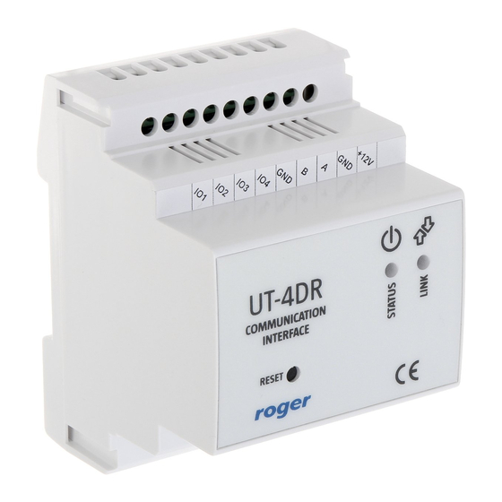
Fig.2 UT-4DR proposed connections diagram in RACS system. 2.2 LED indicators UT-4DR is equipped with two LED diodes indicating actual state of a device (Fig.2). Bi-color LED LINK informs about currently going transmission in RS485 bus, where green color means data sending, while red data receiving by a module. -
Page 6: Input/Output Lines
2012-09-21 2.4 Input/Output lines UT-4DR has 4 lines of general purpose indicated as IO1...IO4. These lines can be used individually as independent inputs or outputs. They can work with maximal voltage of 15VDC (in comparison to device’s power supply ground) no matter if configured as input or output. Input lines are activated by low logical state (connecting the line to ground). -
Page 7: Rs485 Communication Bus
E-M noise presence it is recommended to use shielded cable (FTP). By default every UT-4DR interface is in DHCP mode. In case of direct connection between PC computer and UT-4DR module (such situation takes place usually for local module configuration before connecting it to LAN network) there is a possibility to deactivate DHCP in the module. -
Page 8: Installation Guidelines
ONFIGURATION 3.1 Configuration using web browser It is possible to configure UT-4DR interface using its embedded WWW page. To do this, please type module’s IP address (ex.192.168.0.38) in web browser address field, and log in as a default user with the following parameters: ... -
Page 9: Configuration Using Telnet Protocol
(TCP Stat) and possibility to module’s firmware change (FW Upgrade). The view of mobile devices website is shown below in Fig.6. Restart Zakładka zawierająca przycisk Reboot służący do zdalnego restartu modułu UT-4DR. To go back to main configuration window use button with house picture placed in top right corner of each configuration window. -
Page 10: Memory Reset
UT-4DR. 3.3 Memory reset In order to get back to UT-4DR module’s factory settings it is required to stop any communication with module (web browser and/or Telnet), put two jumpers as shown in Fig.8 and press RESET button in the front panel. Reset procedure lasts about 5 seconds and when it is finished LED STATUS diode blinks 3 times indicating success of the operation. -
Page 11: Firmware Update Procedure
In Firmware Upgrade tab, press Wybierz button to choose on your computer a file containing new firmware. Press Send button to send file to the UT-4DR module and change its firmware. During firmware modification all I/O lines are deactivated. After sending new firmware to module, please reset it by pressing Reboot button in the web page. -
Page 12: Technical Specification
UT-4DR v1.0 Instruction manual Rev.B 2012-09-21 4. T ECHNICAL SPECIFICATION Parameter Value Supply voltage 10...15 VDC Current consumption Average 55 mA @ 12V DC, Environmental class Class II, indoor conditions, temp.:- 10°C +40°C, relative humidity: 0 - 75% (no condensation) Dimensions 62x85x73mm (WxHxD);...
Need help?
Do you have a question about the UT-4DR and is the answer not in the manual?
Questions and answers