Table of Contents
Advertisement
Quick Links
Advertisement
Table of Contents

Related Manuals for Amb-OS Media AMR-100


Summary of Contents for Amb-OS Media AMR-100
- Page 1 Amb-OS Media, LLC AMR-100 Operations Manual Firmware 2.28 Revision 40 09/22/14...
- Page 2 WARNING One AMR-100 receiver can be controlled by multiple Amb-OS User Interface programs on different computers, but without proper precautions, unpredictable results can be experienced. Rev. 40 – Firmware Version 2.28 ©...
-
Page 3: Table Of Contents
TABLE OF CONTENTS CONTENTS OF PACKAGE ........................6 INTRODUCTION ............................6 General Information ..........................6 Overview of Connections and controls ....................7 Getting Started ..........................7 RF ..............................7 Audio ............................. 8 Ethernet Connection ........................8 Power ............................. 8 Boot Process ..........................9 Error Conditions .......................... - Page 4 Digital ............................47 Streaming ............................48 Playback after a power loss ........................48 HTML INTERFACE ..........................49 Access to the AMR-100 Web page ......................49 HTML Menus ............................50 Diagnostic Menus .......................... 50 Rev. 40 – Firmware Version 2.28 ©...
- Page 5 General Diagnostics Menu ......................50 System Statistics ........................50 Scheduled Event List ......................54 Trigger Event Lists ........................56 Command Interface ......................... 57 Satellite Diagnostics ........................63 TROUBLESHOOTING CHART ......................64 APPENDIX ..............................66 Definitions .............................. 66 Permission Portal ........................... 68 Logging Into the Site ........................
-
Page 6: Contents Of Package
Email support@amb-os.com Program Requests http://www.focussat.net/cgi-bin/ambos/permissions WARNING To receive programs on the AMR-100, login into the Amb-OS program permission portal (http://www.amb-os.com/permissions) to request programs. Without requesting programs, the AMR-100 will not receive any programs. Rev. 40 – Firmware Version 2.28 ©... -
Page 7: Overview Of Connections And Controls
Connect the RF cable first. If other equipment uses the same satellite dish as the AMR-100 receiver, verify the one providing power to the LNB, because only one device may supply power to the LNB. With multiple devices, refer to the detailed... -
Page 8: Audio
The default setting for the IP address setting uses DHCP. If the network does not use DHCP, then the AMR-100 will not connect to the network or the Internet and result in an alarm mode after applying power. -
Page 9: Boot Process
Boot Process After the AMR-100 receives power, it begins its startup process, which takes about twenty seconds. 1. Reset the drive 2. Initialize drive 3. Scanning file system 5. Finished booting 4. Initialize receiver Relay #6 should be clear (no alarms) If the receiver has been setup correctly, the “Sat,”... -
Page 10: Error Conditions
Error Conditions If the RF cable to the satellite dish is not connected or not functioning properly, but the Ethernet cable is connected, properly configured and connected to the Internet, relay #6 will be active (dark) and the “Sat” box will be clear. To verify the connection, see the RF installation section. -
Page 11: General Description
The AMR-100 receiver does not receive programs in a real time audio transmission on a schedule set by the service provider that must be played or recorded at the time the program is sent. The AMR-100 receives programs as audio files sent via a satellite RF carrier faster than real time and stored on an internal hard drive. -
Page 12: Classic Dvb Pids
3. A program can be recorded back the AMR-100. This can be used to time shift a live program. The name of the file must have the “T” before the name and the “MP2” extension (Tprogram-name.MP2). -
Page 13: Target Maps
Possible combinations for the analog ports: 1. Target 1 (T1) and Target 2 (T2) used as stereo outputs. 2. T1 as a stereo output and T2 as two mono output ports (T2L and T2R). 3. T1 as two mono outputs (T1L and T1R) and T2 as a stereo output. 4. -
Page 14: Digital Ports
Stand Alone Playlist Editor www.amb-os.com/support.html) for a complete explanation of playlists. Triggers Triggers initiate an action on the AMR-100 from an external source. Triggers have many options including time limitations. To get a complete understanding of them see the Amb-OS User Interface (UI) Software Playlist Manual. -
Page 15: Commands
Command strings can be as specific as “PLAY-TTT5-06-07-14” or as general as “PLAY.” The AMR-100 can have 256 total triggers (input closures and commands). -
Page 16: Relay Description
#6 (fault indicat ion). Time Sync by Relay #5 To keep station clocks synchronized, a time pulse can be used from the AMR-100. Every hour relay closes for one second as a time sync pulse. This can be at any minute and second of the hour (HH:00:00 or HH:54:45). -
Page 17: Program Use Of Relays #5 And #6
Closure Map section). WARNING If assigning relays to a programming function without disabling the alarm “Clock Interval,” the AMR-100 can produce unpredictable results. The “Relay Map” does not change automatically when the alarm “Clock Intervals” relays are used for programming functions. -
Page 18: Closure Default States
Closure Default States The state of the relay determines what happens when a command is sent. When a program sends a command to the closure, here is what happens with each state. 1. OFF: The relay maintains its current state. If it was closed, it will stay closed. 2. -
Page 19: Resetting The Receiver's Display To Its Default Setting
Resetting the receiver's display to its default setting At times it may be necessary to reset the AMR-100 to the factory settings. If the display contrast setting (see LCD Settings section) made the display unreadable, the AMR-100 must be reset. -
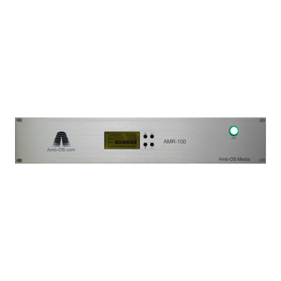
Page 20: Detailed Description And Operations
DETAILED DESCRIPTION AND OPERATIONS Front Panel Description The front panel display gives the status of the receiver. The main screen shows relays, audio output, and the status of the RF and Ethernet (see Front Panel section). [UP] arrow Back Front Panel Buttons To the right of the display are four buttons: The [UP] and [DOWN] arrows: Select different options... -
Page 21: Rear Panel Description
– Standard RJ-45 Ethernet network cable connection 5. Reset Switch Reboots the receiver without performing a power recycle. WARNING Resetting the AMR-100 will stop the audio playback until the AMR-100 has finished booting. 6-15. Audio outputs: Two sets of two stereo analog outputs correspond to the digital outputs. They are listed in order from left to right. -
Page 22: Installation
RF connector and the coax cable connected to the DC Block and then to “Output 2.” To connect the RF to the AMR-100 if more than one Wegener receiver or other satellites receivers is connected to the satellite antenna or the antenna’s LNB is being powered from an outboard power supply, refer to the instructions in “RF with multiple... -
Page 23: Rf With 1 Wegener Unity® 4000 Receiver
DC block on the input on the AMR-100 To have the AMR-100 to provide power to the LNB, merely install the DC Block on the Wegener Unity ® 4000 receiver and swap the RG-6 cables coming from the splitter. Remember, in order for a receiver to power the LNB through the supplied splitter it must be connected to the power pass port (see #3 above). -
Page 24: Rf With Multiple Receivers
With more than one Wegener Unity 4000 receiver or other satellite receivers connected to the satellite antenna and have an open port on a multiple port splitter, install the AMR-100 to the open port per the following instructions: 1. Install the provided DC Block on the AMR-100 receiver’s RF connector. -
Page 25: Using Multiple Splitters
4000 receiver or other receiver connected to the satellite antenna and no open splitter ports, install a splitter before one of the receivers. 1. Install the provided DC Block on the AMR-100 receiver’s RF connector. 2. Disconnect the RF cable from one of the receivers. - Page 26 4000 DC Block RF to other equipment It is recommended DC Pass that a DC block be put on the other piece of equipment. AMR-100 RF from a multiple splitter Rev. 40 – Firmware Version 2.28 © 2014...
-
Page 27: Audio
Audio Analog The analog audio connectors use standard XLR connectors. Each of the two ports can be played in stereo (2 stereo ports), all mono (4 mono ports) or mixed (1 port stereo and the other 2 mono channels). Left Right Left Right... -
Page 28: Ethernet
If a program looses some packets during transmission or if an entire program is missed, the AMR-100 communicates to the uplink server to retrieve the missing packets and restore the program. This virtually guarantees no missing programs. -
Page 29: Serial Port
General Use: The RS-232 serial port sends text commands to the AMR-100 to trigger programs to play. The AMR-100 does not send any information out the serial port for troubleshooting or diagnosis. Technical: The RS-232 serial port connections Three wire modem cable (transmit, receive and ground) •... - Page 30 Example of output closure wiring. The following diagram shows the use the internal +5V pull-up source connected to pin 13. The following diagram shows the use of an external pull-up source. Pin 13 is not connected to anything and the external voltage source connects to pins 24, 11, 21 and 8. Rev.
-
Page 31: Operations
“System Statistics” from the “HTML Command Interface.” Disabled (“*” not on screen): If the Emergency Message is not enabled, the AMR-100 will not receive special or emergency broadcasts regardless of whether TMAP7 has been mapped to an output. -
Page 32: Authorized Message
The network administrator can disable a receiver. If that happens, the following message appears on the screen with only the message line below it: Deauthorized In the event the AMR-100 becomes “De-authorized,” Call the Amb-OS support line to have it restored to normal operation. (877) AMB-OS2U or (877) 262-6728 Rev. -
Page 33: Front Panel Menu Options
Front Panel Menu Options The following chart is a tree of all the options in the front panel setup. Settings Firmware Serial IP_Addr Alarm DHCP IP Addr Gateway Netmask Server 1-4 Port 1-4 Cmd Addr Cmd Port Web Port Clock Interval Closure Map Minutes P1LS... - Page 34 To get to the “Settings Menu,” press the [ENTER] button once. Firmware: 2.28 (or current version) Serial No: 2001000 (local serial number) Addr: DHCP (default or the internal IP address of the AMR-100 – 192.168.1.150) *Clock Interval *Closure Map *Target Map...
-
Page 35: Settings Menu
*RpPort4 b. “Output 5” c. “Output 6” *LdSrvr1 6. Press [BACK] to save and return to the “IP Addr” submenu *LdPort1 Turn the alarm setting to “OFF” if the AMR-100 does not have a LdPort2 *LdSrvrt2 network connection. *LdPort2 *DHCP... -
Page 36: Ip Addr
9. Repeat steps #7 and #8 until the desired IP address has been entered 10. Press [ENTER] on the last digit to save the new address and exit the settings menu When changing the AMR-100 from a dynamic IP address (DHCP = “Yes”) to a static IP address (DHCP = “No”) the... -
Page 37: Gateway
Networks use the netmask to separate network segments. Normally, a local network uses a mask of 255.255.255.0 and the AMR-100 uses that as the default and does not need to be changed. The network administrator can give an alternate netmask if necessary. -
Page 38: Rpsrvr/Ldsrvr, Command Address And Ports
4 represent the reporting servers (were data and reports are sent). The load servers 1-4 represent the backfill servers. command address specifies the IP address used by the AMR-100 to communicate with a browser to use the HTML Interface. The... -
Page 39: Webport
1. Press [ENTER] and [ENTER] to edit the settings 2. Press the [DOWN] arrow to highlight “DHCP” or the IP address of the AMR-100 3. Press [ENTER] to change the settings 4. Press [DOWN] until “WebPort” is highlighted 5. Press [ENTER] to change the settings 6. -
Page 40: Clock Interval
Seconds The AMR-100 does not check to see if the same relay is used for the time sync and alarm so be careful to check which, if either relay for each function. -
Page 41: Closure Map
*Closure Map This allows changing the programming relay Closure Map assignments. The “Closure Map Table” section lists the default assignments and states. The names are listed in the illustration to the right. The numbers in the name are P1LS the relay numbers. All six relays can be used if the P1LE “Clock Interval”... -
Page 42: Relay Test Menu
Relay Test Menu To test and the input closures and verify the output relays, press [UP] and [DOWN] arrows at the same time while in the “Closure Map” menu. To move between the output closures, use the [UP] and [DOWN] arrows. The [DOWN] arrow moves the cursor to the right and the [UP] arrow moves the cursor to the left. -
Page 43: Target Map
*Target Map This menu allows the target map assignments to be changed to any of the to any of the analog targets. The default mappings are: Date Setup TMAP1 = T1 (stereo) TMAP1: Stereo 1 TMAP2 = T2 (stereo) TMAP2: Stereo 2 TMAP3 = T1L (mono) TMAP3:... -
Page 44: Lcd Settings
Use this to change the contrast of the display. Be very LCD Settings careful, because the display can be made unreadable. Resistance Ratio Resetting the AMR-100 to its default settings will fix it. Reference Voltage From the main screen: 1. Press [ENTER] and press [ENTER] again to Setup... -
Page 45: Date Menu
Date Menu In a few minutes after connecting the RF to the AMR-100 it will sync its time to GPS time embedded in the RF carrier. The carrier sends and the receiver changes the time to reflect the Zone Daylight Saving Time setting. -
Page 46: Time Zone
2. Press the [UP] or [DOWN] arrow to highlight “Date” 3. Press [ENTER] to enter the “Date” settings After the AMR-100 has synced its time with the RF carrier, pressing [ENTER] highlights the zone setting and bypasses the date and time setting. -
Page 47: Audio Playback Description
Port 2-L and Port 2-R) The AMR-100 mixes the left and right channel to mono when sent out a mono port. A stereo program sent out Port 1-L will have the left and right mixed to mono on that port. -
Page 48: Streaming
The AMR-100 stores the time a program starts and the time it would end. When the AMR-100 loses power or is rebooted or is reset, it calculates the position in the program where it would have been without the interruption. -
Page 49: Html Interface
HTML INTERFACE Access to the AMR-100 Web page To access the AMR-100 remotely through the built in web interface, the AMR-100 needs to be connected to the same network as the computer used by the AMR-100. Open an Internet browser window and enter the IP Address of the receiver into the address line of the browser. -
Page 50: Html Menus
19506176 Time: 09:03 07/01/10 Zone: Mountain System Statistics DST: GMT Time: 15:03 07/01/10 This shows the settings and activity of the AMR-100 Eastern Time: 11:03 07/01/10 Time Running: 148:37 General Statistics: Addresses and general settings RECEIVER STATISTICS Receiver Statistics: RF strength and quality... - Page 51 Greenwich Mean Time and date Eastern Time: Current Eastern Time and it reflects and date Time Running: Number of hours the AMR-100 has been running Receiver Statistics PID(s): The Program Identification number of the carrier RECEIVER STATISTICS Carrier Status: The state of the carrier. “Acquired”...
- Page 52 LNB if this number is not 0. I2C Errors (I squared C – I C): The number of errors the processor has. The AMR-100 will need to be sent back for repairs if this number is not 0. Lost Lock Ev: The number of times or Events (Ev) the receiver lost its lock with the carrier. Any number other than 0 means the satellite dish may not be properly aligned.
- Page 53 Inet Buff Msecs: The number of milliseconds the AMR-100 buffers audio from an Internet stream to reduce audio packet delays. This is set by Amb-OS support personnel. Inet Buff Msecs: The number of milliseconds the AMR-100 buffers audio from an RF stream to reduce audio packet delays.
-
Page 54: Scheduled Event List
Scheduled Event List This page shows the scheduled events in the playlist (see Playlist section). Without a playlist, this will have no entries as shown below. Column Headings Action: The type of event Time: The date and time when the event happens in local time Source: The program to be played (displayed as the Amb-OS system name) Target: The output target... - Page 55 The column labeled “Action” has every event that happens. Every program has at least three entries: OPEN: The AMR-100 opens the program file and reads the first block of data one second before the scheduled playback to ensure the program starts on time.
-
Page 56: Trigger Event Lists
Trigger Event Lists This page lists the events triggered by an input closure text command sent via the RS-232 serial port or satellite. Local triggers numbers use numbers below 1000 and program providers use numbers above 1000. The page lists the input closures text commands numerical order as they are numbered in the playlist. -
Page 57: Command Interface
Command Interface This page allows commands to be sent to the receiver. Type the command into the input window and press [ENTER] or click on “Execute” to send the command to the AMR-100. The case of the command does not matter. - Page 58 The command RELAY 1 ON closes relay #1. This is extremely useful in testing relays. Closing relays should be used with extreme caution after completing the wiring to the AMR-100. If the system alarm has been wired and “RELAY 6 ON” is issued, the alarms will activate. Likewise, if the clock synchronization circuit has been wired and the command “RELAY 5 ON”...
- Page 59 Daylight Saving Time (DST). Setting “DST” to “ON” automatically changes Eastern time from -5 GMT to -4 GMT during Daylight Saving Time (DST). In Hawaii, set “DST” to “NO” and the AMR-100 will remain -10 GMT even during Daylight Saving Time (DST).
- Page 60 “NEWIP” HTML Command Interface. Syntax: DHCP ON or DHCP OFF WARNING Setting DHCP to “OFF” requires setting the AMR-100 IP address manually. NEWIP #.#.#.# This changes the AMR-100’s address. The new IP address must be changed in the Amb-OS User Interface and the browser has to have the new IP address.
- Page 61 “AUDPLAY” command. The “Audplay” command needs the exact name of the program on the AMR-100. Program names can be seen at http://www.amb-os.com/programs. Take designation on http://www.amb- os.com/programs (MMMM_PPPP) and add the date (MM-DD-YY), the number of parts (PN-TP) and the MP2 extension.
- Page 62 The TMAP section under the system statistics shows the current mapping on the AMR-100 receiver. Any of the six TMAPs (TMAP1 to TMAP6) can be assigned to any one of the six targets: T1 = Port 1 stereo T1L = Port 1 mono –...
-
Page 63: Satellite Diagnostics
Satellite Diagnostics The AMR-100 records various statistics about the health of the RF carrier. Two summary tables are provided to assist in troubleshooting problems. 1. The 1-Minute Summary takes a snap shot every minute and records any of errors in that minute. -
Page 64: Troubleshooting Chart
2. If only the “Inet” indicator is clear, check the “No ‘Inet’ indication” 3. If the “Lan” indicator is clear, check the “No ‘Lan’ Indication” 4. Verify program permissions for the AMR-100 at www.focussat.net/cgi-bin/ambos/permissions 5. Check the feed for program issues 6. - Page 65 No Audio Files are not on the receiver 1. If the file is not on the receiver, check “No files playback Audio improperly connected being received” Audio not be monitored correctly 2. Check the audio connections Playlist is incorrect 3. Verify the proper audio port or target is being used 4.
-
Page 66: Appendix
DVB or Digital Video Broadcast – The standard for digital broadcasts on satellite www.dvb.org. See MP2. Dynamic IP Address – The IP address gets set automatically by the network router. The IP address can change if the router reassigns addresses. In the AMR-100, the DHCP is set to “On.” See Static IP Address. - Page 67 PID or Program ID or Identifier – The unique ID of the program used by a receiver on a standard carrier. Static IP Address – The IP address of a device is set to fixed address. In the AMR-100, DHCP is set to “No.”...
-
Page 68: Permission Portal
The AMB-OS User Interface has the serial number in the “System Settings.” • On the front panel of the AMR-100, press the [ENTER] button once on the AMR-100. • To retrieve a lost or forgotten password, enter in the AMR-100’s serial number and click on “Email me a password.”... -
Page 69: Requesting And Deleting Program Permissions
The Amb-OS Permission Portal lists all available programs on the left, all the program with permissions for the AMR-100 on the right and the definitions of the ministries under the table. Requesting and deleting program permissions Use the left window to... -
Page 70: Contact Information
“Request permissions.” A request gets sent to the appropriate ministry and they will grant the AMR-100 permission to receive the program. Some ministries may want more information before granting program permissions. Click on “Clear all” to clear the highlighted program(s). -
Page 71: Deleting Programs
Deleting Programs The process to delete a program permission is the same as requesting permissions. Highlight the program(s) that will no longer be used. To select multiple programs, use the control key with the left mouse click. After selecting the program(s) to be deleted, click on “Remove permissions.”...
Need help?
Do you have a question about the AMR-100 and is the answer not in the manual?
Questions and answers